




- 98% satisfied customers
- 72h delivery
- 30 dni na zwrot
Description
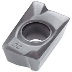
DCGT 070204 turning insert – positive 55° rhombus
| Technical data | |
|---|---|
| Side length l | 7.75 mm |
| Insert thickness s | 2.38 mm |
| Hole diameter d1 | 2.8 mm |
| Corner radius rε | 0.4 mm |
| ANSI code | DCGT 21.51 |

Cutting data for the DCGT 070204 insert for aluminum and nonferrous metals
finishing, semi-finishing, and roughing — ISO N group
| Material | Finishing | Semi-finishing | Roughing | ||||||
|---|---|---|---|---|---|---|---|---|---|
| Vc [m/min] | Feed f [mm/rev] | ap [mm] | Vc [m/min] | Feed f [mm/rev] | ap [mm] | Vc [m/min] | Feed f [mm/rev] | ap [mm] | |
| NAluminum and nonferrous materials | 375-2400 | 0.1 | 0.1 | 40-240 | 0.15 | 2.05 | 40-240 | 0.2 | 4 |
K10 carbide positive insert – applications and design
single-sided 55° diamond with a hole and chip breaker
The DCGT 070204 turning insert is a positive, single-sided indexable insert made of fine-grain K10 grade cemented carbide, designed for turning aluminum and nonferrous metals. The D shape, a rhombus with a 55° corner angle, facilitates profile machining and transitions between the end face and cylindrical surface of a workpiece. The 7° clearance angle (letter C) indicates a positive design with a sharp edge that uses one side of the insert — two 55° corners. The corner radius rε 0.4 mm favors finishing at low feed rates and low cutting forces. A countersunk hole and a single-sided chip breaker (type T according to ISO 1832) secure the insert and assist evacuation of the long ribbon chips typical of aluminum alloys.
Key benefits of the K10 carbide insert
- Two cutting edges — 2 corners with a 55° angle on one side of the insert; the positive geometry prevents use of the other side.
- K10 grade for nonferrous metals — fine-grain carbide for aluminum, brass, and bronze in the ISO N group, with a sharp, polished edge.
- Corner radius rε 0.4 mm — finishing at low feed rates, low surface roughness after turning.
- A positive clearance angle of 7° reduces cutting forces and performs well on thin-walled workpieces prone to deflection.
- Tolerance class G (ground): inscribed circle accuracy IC ±0.025 mm provides precise, repeatable cutting edge positioning.
- Dimensions conforming to ISO 1832: IC 6.35 mm (1/4″), thickness 2.38 mm, side length 7.75 mm — fit holders for size 07 D inserts.
Applications and cutting data selection for the diamond-shaped insert
The DCGT 070204 insert (also written without a space as dcgt070204) performs well in finish turning of bushings, pistons, and housings made of aluminum alloys, as well as brass and bronze components. Calculate spindle speed using n = 1000·Vc/(π·D): for a shaft with a diameter of 40 mm at Vc = 600 m/min, the result is approximately 4775 rpm. Aluminum allows high cutting speeds, so the sharp, polished edge of the GT geometry limits built-up edge formation and maintains low surface roughness. Tolerance class G, a ground profile with an IC accuracy of ±0.025 mm, provides repeatable cutting edge positioning after the insert is rotated in its pocket.
This indexable cemented carbide insert is single-sided, providing two cutting edges — once both corners are worn, the insert is replaced. For external turning, choose holders with a pocket for a size 07 rhombic insert, such as SDJCR/L or SDNCN; for internal turning of small holes, use S10K–S20R boring bars with a head for the same insert. When selecting cutting data, maintain a high cutting speed and ample coolant to prevent chips from adhering to the cutting edge. Grade K10 indexable inserts are supplied by the Korean brand Horn.
▲
Application limitation
Grade K10 and the sharp GT geometry are designed for nonferrous metals — for turning steel and cast iron choose an insert from group ISO P or M. On ferrous materials, the thin, polished edge wears quickly.
Rhombic insert designation decoder according to ISO 1832
how to read the DCGT 070204 code — positions 1–7 of the designation
Designation DCGT 070204 according to the standard ISO 1832: 4 letters describe geometry and construction, 3 numeric codes describe dimensions. Each field has a number, an icon, and a brief description.
Compatible turning tools
holders and boring bars for a 07 rhombic insert — external and internal turning
SDHCR/L 0808 E078×8 × 70 mmR right-hand
←L left-hand
→
←L left-hand
→
SDHCR/L 1010 E0710×10 × 70 mmR right-hand
←L left-hand
→
←L left-hand
→
SDHCR/L 1212 F0712×12 × 80 mmR right-hand
←L left-hand
→
←L left-hand
→
SDHCR/L 1616 H0716×16 × 100 mmR right-hand
←L left-hand
→
←L left-hand
→
SDJCR/L 0808 E078×8 × 70 mmR right-hand
←L left-hand
→
←L left-hand
→
SDJCR/L 1010 E0710×10 × 70 mmR right-hand
←L left-hand
→
←L left-hand
→
SDJCR/L 1212 F0712×12 × 80 mmR right-hand
←L left-hand
→
←L left-hand
→
SDJCR/L 1616 H0716×16 × 100 mmR right-hand
←L left-hand
→
←L left-hand
→
SDNCN 0808 E078×8 × 70 mmR right-hand
←L left-hand
→
←L left-hand
→
SDNCN 1010 E0710×10 × 70 mmR right-hand
←L left-hand
→
←L left-hand
→
SDNCN 1212 F0712×12 × 80 mmR right-hand
←L left-hand
→
←L left-hand
→
SDNCN 1616 H0716×16 × 100 mmR right-hand
←L left-hand
→
←L left-hand
→
S12K SDXCR/L-07Ø12 | Ømin 17 mm | L=125R right-hand
←L left-hand
→
←L left-hand
→
S10K SDPCR/L-07Ø10 | Ømin 13 mm | L=125R right-hand
←L left-hand
→
←L left-hand
→
S12K SDPCR/L-07Ø12 | Ømin 16 mm | L=125R right-hand
←L left-hand
→
←L left-hand
→
S10K SD-CR/L-07Ø10 | Ømin 14 mm | L=125R right-hand
←L left-hand
→
←L left-hand
→
S12K SD-CR/L-07Ø12 | Ømin 17 mm | L=125R right-hand
←L left-hand
→
←L left-hand
→
S12x16P SD-CR/L-07Ø16 | Ømin 17 mm | L=150R right-hand
←L left-hand
→
←L left-hand
→
S10K SDQCR/L-07Ø10 | Ømin 13 mm | L=125R right-hand
←L left-hand
→
←L left-hand
→
S10x16P SDQCR/L-07Ø16 | Ømin 13 mm | L=150R right-hand
←L left-hand
→
←L left-hand
→
S12K SDQCR/L-07Ø12 | Ømin 16 mm | L=125R right-hand
←L left-hand
→
←L left-hand
→
S12x16P SDQCR/L-07Ø16 | Ømin 16 mm | L=150R right-hand
←L left-hand
→
←L left-hand
→
S16P SDQCR/L-07Ø16 | Ømin 21 mm | L=170R right-hand
←L left-hand
→
←L left-hand
→
S20R SDQCR/L-07Ø20 | Ømin 25 mm | L=200R right-hand
←L left-hand
→
←L left-hand
→
S10K SDUCR/L-07Ø10 | Ømin 13 mm | L=125R right-hand
←L left-hand
→
←L left-hand
→
S10x16P SDUCR/L-07Ø16 | Ømin 13 mm | L=150R right-hand
←L left-hand
→
←L left-hand
→
S12K SDUCR/L-07Ø12 | Ømin 16 mm | L=125R right-hand
←L left-hand
→
←L left-hand
→
S12x16P SDUCR/L-07Ø16 | Ømin 16 mm | L=150R right-hand
←L left-hand
→
←L left-hand
→
S16P SDUCR/L-07Ø16 | Ømin 21 mm | L=170R right-hand
←L left-hand
→
←L left-hand
→
S20R SDUCR/L-07Ø20 | Ømin 25 mm | L=200R right-hand
←L left-hand
→
←L left-hand
→
Frequently asked questions about the DCGT 070204 insert
use, turning tool selection, and turning parameters
Two — the diamond has 2 acute corners 55°, and the positive geometry with a 7° clearance angle allows only one side of the insert to be used. Once both corners are worn, the insert is replaced without flipping it over.
Holders with a pocket for a 07 rhombic insert (IC 6.35 mm): for external turning SDHCR/L, SDJCR/L and SDNCN with cross sections of 8×8–16×16 mm; for internal turning, boring bars S10K–S20R with an SD-CR/L, SDPCR/L, SDQCR/L or SDUCR/L head. The letter R indicates a right-hand version, and L a left-hand version.
Only in corner radius: 0.2 mm is used for precision finishing of thin profiles, 0.4 mm is a general-purpose finishing version, while 0.8 mm is selected for higher feed rates and depths of cut. The remaining dimensions (IC 6.35 mm, thickness 2.38 mm) are identical.
This is not recommended — grade K10 and the sharp GT geometry are designed for aluminum and nonferrous metals (group ISO N). For turning steel or cast iron, choose an insert from group ISO P or M, because the polished edge wears quickly on ferrous materials.
Product accessories


Reviews
No customer reviews for the moment.
Shipping
All orders are delivered by courier company GLS. For orders exceeding 369 PLN gross shipping is FREE
| Courier GLS | Przelew24 / Prepayment | 14,76 zł gross | Delivery time 1 working day |
| Courier GLS | Cash on delivery | 17,26 zł gross | Lead time 1 working day |
Recommended for you


Viewed products

This website uses its own and third-party cookies to improve our services and show you advertising related to your preferences by analyzing your browsing habits. To give your consent to its use, press the Accept button.
Cookie preferences
Functional cookiesTechnical
Functional cookies are strictly necessary to provide the services of the shop, as well as for its proper functioning, so it is not possible to refuse their use. They allow the user to browse through our website and use the different options or services that exist on it.
Advertising Cookies
These are cookies that collect information about the advertisements shown to users of the website. They can be anonymous, if they only collect information about the advertising spaces shown without identifying the user, or personalised, if they collect personal information about the user of the shop by a third party, for the personalisation of these advertising spaces.
Analytics cookies
Collect information about the user's browsing experience in the shop, usually anonymously, although sometimes they also allow the user to be uniquely and unequivocally identified in order to obtain reports on the user's interests in the products or services offered by the shop.