





Description
| Technical data | |
|---|---|
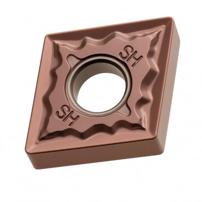
| Side length l | 12.7 mm |
| Insert thickness s | 4.76 mm |
| Hole diameter d1 | 5.16 mm |
| Corner radius rε | 1.2 mm |
| ANSI code | CNMG 433 |
finishing, semi-finishing and roughing — ISO P and M groups
| Material | Finishing | Semi-finishing | Roughing | ||||||
|---|---|---|---|---|---|---|---|---|---|
| Vc [m/min] | Feed f [mm/rev] | ap [mm] | Vc [m/min] | Feed f [mm/rev] | ap [mm] | Vc [m/min] | Feed f [mm/rev] | ap [mm] | |
| PSteel | 220-400 | 0.1-0.2 | 0.5-2 | 130-200 | 0.22-0.44 | 1-4 | 170-190 | 0.22-0.44 | 1-4 |
| MStainless steel | 220-320 | 0.1-0.2 | 0.5-2 | 70-100 | 0.22-0.44 | 1-4 | 55-75 | 0.22-0.44 | 1-4 |
double-sided 80° diamond with a hole and chip breaker
The CNMG 120412 turning insert is a double-sided, rhombic indexable insert made of grade H6310 cemented carbide, designed for turning steel and stainless steel. Shape C, a rhombus with a 80° corner angle, combines a rigid, strong corner with good clearance during longitudinal turning and facing. The negative geometry with a 0° clearance angle allows both sides of the insert to be used — providing a total of four cutting edges. The mounting hole with a double-sided chip breaker (type G according to ISO 1832) controls chip flow and breaking during continuous cutting. The corner radius rε of 1.2 mm and thickness s of 4.76 mm provide the cutting edge with additional strength for roughing with a large chip cross section.
The CNMG 120412 insert (also written without a space as cnmg120412) is suitable for roughing and semi-finishing shafts, bushings, and flanges made of structural steels, as well as stainless steel components. The 80° corner angle allows one cutting edge to machine both cylindrical surfaces and faces, reducing the number of tool changes in the cycle. Calculate spindle speed using the formula n = 1000·Vc/(π·D): for a shaft diameter of 80 mm at Vc = 200 m/min, the result is approximately 796 rpm. For workpieces with varying cross sections, maintain a constant surface speed by adjusting spindle speed after each change in diameter.
The 1.2 mm corner radius is best utilized at greater depths of cut ap and feed rates of 0.22–0.44 mm/rev, where the large corner dissipates heat and resists chipping. For stainless steels, maintain a cutting speed of 55–320 m/min and a constant, uninterrupted feed to avoid work hardening of the layer being cut and accelerated cutting edge wear. Rigid workpiece clamping and short holder overhang reduce vibration with such a large corner radius. For finishing passes, select a smaller radius from the same family, such as 0.4 or 0.8 mm. Indexable inserts in grade H6310 are supplied by the Korean brand Horn.
Grade H6310 is not intended for steels hardened above 45 HRC — for hard turning, select the version CNMG 120412 with a cubic boron nitride (CBN) cutting edge.
how to read the CNMG 120412 code — positions 1–7 of the designation
Designation CNMG 120412 according to the standard ISO 1832: 4 letters describe geometry and construction, 3 numeric codes describe dimensions. Each field has a number, an icon, and a brief description.
holders with a 12 diamond-shaped pocket — external and internal turning
use, turning tool selection, and turning parameters
Four — the diamond has 2 corners per side, and the negative geometry (0° clearance angle) allows both sides of the insert to be used. Once an edge becomes dull, simply rotate the insert in its pocket without changing the holder.
Holders with a 12 diamond-shaped pocket (IC 12.7 mm): for external turning TCLNR/L and PCLNR/L (entering angle 95°), PCBNR/L, PCMNN, TCMNN, TCZNN and TCKNR/L with cross sections of 16×16–40×40 mm; for internal turning, boring bars S20R–S50V with a TCLNR/L or PCLNR/L head.
Only in corner radius: 0.4 mm is used for finishing at low feed rates, 0.8 mm is the general-purpose version, and 1.2 mm is selected for roughing at feed rates up to 0.44 mm/rev. The remaining dimensions (IC 12.7 mm, thickness 4.76 mm) are identical.
Yes — grade H6310 covers group ISO M20-M40. Maintain a cutting speed of 55–320 m/min, a constant feed, and continuous emulsion cooling: austenitic steel conducts heat poorly and work-hardens when cutting is too slow.
No customer reviews for the moment.
All orders are delivered by courier company GLS. For orders exceeding 369 PLN gross shipping is FREE
| Courier GLS | Przelew24 / Prepayment | 14,76 zł gross | Delivery time 1 working day |
| Courier GLS | Cash on delivery | 17,26 zł gross | Lead time 1 working day |
This website uses its own and third-party cookies to improve our services and show you advertising related to your preferences by analyzing your browsing habits. To give your consent to its use, press the Accept button.


