





- 98% satisfied customers
- 72h delivery
- 30 dni na zwrot
Description
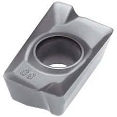
APKT 100305 PDR milling insert – rectangular 85°
| Technical data | |
|---|---|
| Insert shape | Rectangular 85° |
| Side length l | 10 mm |
| Insert thickness s | 3.5 mm |
| Corner radius rε | 0.5 mm |
| Clearance angle | 11° (positive) |
| Tolerance | class K |
| Entering angle κ | 90° (shoulder) |
| Cutting edges | 2 |
| Grade / coating | H6310 PVD |

Indexable insert – milling parameters for steel and stainless steel
shoulder and pocket milling with a 90° shoulder milling head — ISO P and M groups
| Material | vc [m/min] | Feed per tooth fz [mm] | ap [mm] | ae [% D] |
|---|---|---|---|---|
| PSteel | 130-200 | 0.10-0.20 | 1.0-4.0 | 30-70 |
| MStainless steel | 70-130 | 0.06-0.15 | 0.5-2.0 | 25-60 |
H6310 carbide insert – applications and design
single-sided 85° rectangle for 90° indexable milling heads
This PDR milling insert is a single-sided, positive indexable insert made of cemented carbide in grade H6310, designed for milling steel and stainless steel. Shape A, a rectangle with a 85° corner angle, combined with a 11° clearance angle, provides positive geometry with low cutting resistance. The insert is mounted in 90° shoulder milling heads, allowing it to machine vertical pocket and shoulder walls. PDR is the manufacturer's geometry suffix and should not be interpreted for the APKT family without a product data sheet.
Key advantages of this milling insert
- Grade H6310 for ISO groups P and M — PVD-coated carbide for structural and alloy steel (P20-P40) and stainless steel (M20-M40).
- Positive 11° geometry — low cutting resistance and power consumption, beneficial with less rigid clamping and thin-walled workpieces.
- 90° entering angle — clean shoulders and straight vertical pocket walls when cutting at the full depth ap.
- Two cutting edges per insert reduce the unit operating cost of the milling head.
- Class K tolerance ensures a uniform seating height for all inserts in the milling head pockets.
- The 0.5 mm corner radius rε combines a smooth machined surface with tip strength.
Selecting milling parameters for the milling insert
This indexable insert is suitable for milling shoulders, pockets and straight vertical walls in structural, alloy and stainless steels. The 90° entering angle directs forces mainly radially, allowing the full depth of the layer being cut to be machined in one pass. Calculate the spindle speed using n = 1000·vc/(π·D): for a milling head diameter of 40 mm at a cutting speed of 160 m/min, the result is approximately 1273 rpm. With a feed per tooth fz of 0.15 mm and five cutting edges in the head, the feed rate vf = fz·z·n is approximately 955 mm/min. This selection combines productivity with a reasonable edge load.
Grade H6310 with a PVD (physical vapor deposition) coating retains hardness and thermal stability even during the interrupted cutting typical of milling. In stainless steels, use a cutting speed near the lower end of the range and a constant feed per tooth to limit work hardening of the layer being cut. Milling inserts in grade H6310 are supplied by the Korean brand Horn. Apply a steady stream of coolant emulsion to stabilize chip breaking and reduce the edge temperature. Select the depth of cut to suit clamping rigidity, as the 90° angle increases the risk of vibration with a long milling head overhang and accelerates corner wear.
▲
Application limitation
Grade H6310 is not intended for hardened steels above 45 HRC. For harder materials, select an insert in grade H8320.
Parallelogram insert designation decoder according to ISO 1832
how to read the APKT 100305 PDR code — designation positions 1–9
Designation APKT 100305 PDR according to the standard ISO 1832: 4 letters describe the geometry and construction, 2 numeric codes describe the dimensions, and the suffix PDR — the wiper edge geometry. Each field has a number, an icon and a brief description.
ISO 1832 designation decoder — how to read the code
1Ashape 2Pangle α 3Ktolerance 4Ttype – 510edge length 603thickness 705radius rε – 7Pangle κ 8Dland α′ 9Rhand
Positions 1–4 · ISO code
1AShape
Parallelogram 85°
2 corners of 85° per side
2PClearance angle
α = 11°
positive, single-sided
3KTolerance
Class K (precision)
ground thickness ±0.025 mm
4TType
Countersunk hole + chip breaker
countersink 40–60°, single-sided chip breaker
Positions 5–7 · dimensions [mm]
510Edge length
l = 10 mm
code 10 → edge length
603Thickness
s = 3.18 mm
between rake faces
705Corner radius
rε = 0.5 mm
code ÷ 10 → radius in mm
PDR suffix · wiper edge
7PEntering angle
κ = 90°
90° angle milling cutters and milling heads
8DWiper land
α′ = 15°
wiper land clearance angle
9RHand
Right-hand
standard clockwise spindle rotation
✓ 2 corners × 1 side = 2 cutting edges
Full designation: APKT 100305 PDR = parallelogram 85° · positive 11° · class K · countersunk hole and chip breaker · l 10 mm · s 3.18 mm · rε 0.5 mm · κ 90° · wiper land 15° · right-hand (R)
Compatible milling heads and indexable milling cutters
APKT 10 pocket — shoulder, pocket and vertical wall milling
ST90 AP10 D16 W16 L120 Z02⌀16 mm | 2 cutting edges | L120 mm | Weldon ⌀16
⌀16
ST90 AP10 D20 W20 L120 Z03⌀20 mm | 3 cutting edges | L120 mm | Weldon ⌀20
⌀20
ST90 AP10 D25 W25 L120 Z03⌀25 mm | 3 cutting edges | L120 mm | Weldon ⌀25
⌀25
ST90 AP10 D32 W32 L120 Z04⌀32 mm | 4 cutting edges | L120 mm | Weldon ⌀32
⌀32
ST90 AP10 D40 W32 L120 Z05⌀40 mm | 5 cutting edges | L120 mm | Weldon ⌀32
⌀40
ST90 AP10 D16 C16 L200 Z02⌀16 mm | 2 cutting edges | L200 mm | Straight shank ⌀16
⌀16
ST90 AP10 D20 C20 L200 Z03⌀20 mm | 3 cutting edges | L200 mm | Straight shank ⌀20
⌀20
ST90 AP10 D25 C25 L200 Z03⌀25 mm | 3 cutting edges | L200 mm | Straight shank ⌀25
⌀25
ST90 AP10 D26 C25 L200 Z03⌀26 mm | 3 cutting edges | L200 mm | Straight shank ⌀25
⌀26
ST90 AP10 D32 C32 L300 Z04⌀32 mm | 4 cutting edges | L300 mm | Straight shank ⌀32
⌀32
HT90 AP10 D20 L87 Z02⌀20 mm | 2 cutting edges | L87 mm | helical
⌀20
HT90 AP10 D25 L105 Z08⌀25 mm | 8 cutting edges | L105 mm | helical
⌀25
HT90 AP10 D32 L115 Z03⌀32 mm | 3 cutting edges | L115 mm | helical
⌀32
HT90 AP10 D40 L130 Z03⌀40 mm | 3 cutting edges | L130 mm | helical
⌀40
TK90 AP10 D40 Z05⌀40 mm | 5 cutting edges | 90° | mounting ⌀16
⌀4090°
TK90 AP10 D50 Z06⌀50 mm | 6 cutting edges | 90° | mounting ⌀22
⌀5090°
TK90 AP10 D63 Z07⌀63 mm | 7 cutting edges | 90° | mounting ⌀22
⌀6390°
TK90 AP10 D80 Z08⌀80 mm | 8 cutting edges | 90° | mounting ⌀27
⌀8090°
TK90 AP10 D100 Z09⌀100 mm | 9 cutting edges | 90° | mounting ⌀32
⌀10090°
TK90 AP10 D125 Z11⌀125 mm | 11 cutting edges | 90° | mounting ⌀40
⌀12590°
TK75 AP10 D63 Z05⌀63 mm | 5 cutting edges | 75° | mounting ⌀22
⌀6375°
TK75 AP10 D80 Z06⌀80 mm | 6 cutting edges | 75° | mounting ⌀27
⌀8075°
TK75 AP10 D100 Z07⌀100 mm | 7 cutting edges | 75° | mounting ⌀32
⌀10075°
Frequently asked questions about the APKT 100305 insert
milling head selection, materials and code meaning
Indexable milling heads and cutters with a pocket for APKT 10 and an entering angle of 90° or 75° — the store's range includes the series ST90 AP10, HT90 AP10, TK90 AP10 and TK75 AP10. It does not fit pockets for larger APKT 1604 inserts.
Two — the rectangle with a corner angle of 85° provides 2 corners, and the positive geometry with a clearance angle of 11° makes the insert single-sided. Once a corner is dull, rotate the insert in the milling head pocket to the second edge.
Grade H6310 with a PVD coating covers structural and alloy steel (ISO P20-P40) and stainless steel (ISO M20-M40). It is not intended for hardened steels above 45 HRC.
The segment APKT describes the insert's basic shape, clearance angle, tolerance and design. PDR is the manufacturer's geometry suffix; its meaning requires the APKT product data sheet.
Product accessories

Indexable milling cutter ST90 AP10 D18 W16 L120 Z02 H Smoxh
Reference: 012161 In stock < 10 items
€50.00
€61.50 brutto

Milling head TK90 AP10 D50 A22 Z06-H Smoxh
Reference: 565302 In stock < 10 items
€68.42
€84.16 brutto

Reviews
No customer reviews for the moment.
Shipping
All orders are delivered by courier company GLS. For orders exceeding 369 PLN gross shipping is FREE
| Courier GLS | Przelew24 / Prepayment | 14,76 zł gross | Delivery time 1 working day |
| Courier GLS | Cash on delivery | 17,26 zł gross | Lead time 1 working day |
Recommended for you


This website uses its own and third-party cookies to improve our services and show you advertising related to your preferences by analyzing your browsing habits. To give your consent to its use, press the Accept button.
Cookie preferences
Functional cookiesTechnical
Functional cookies are strictly necessary to provide the services of the shop, as well as for its proper functioning, so it is not possible to refuse their use. They allow the user to browse through our website and use the different options or services that exist on it.
Advertising Cookies
These are cookies that collect information about the advertisements shown to users of the website. They can be anonymous, if they only collect information about the advertising spaces shown without identifying the user, or personalised, if they collect personal information about the user of the shop by a third party, for the personalisation of these advertising spaces.
Analytics cookies
Collect information about the user's browsing experience in the shop, usually anonymously, although sometimes they also allow the user to be uniquely and unequivocally identified in order to obtain reports on the user's interests in the products or services offered by the shop.