 Polski





- 98% satisfied customers
- 72h delivery
- 30 dni na zwrot
Description
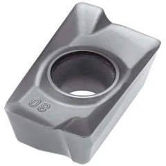
WCMX 06T308 carbide insert – for indexable drills 80°
| Technical data | |
|---|---|
| Side length l | 6.14 mm |
| Insert thickness s | 3.97 mm |
| Hole diameter d1 | 3.7 mm |
| Corner radius rε | 0.80 mm |
| ANSI code | WCMX 32.52 |
| Shape / included corner angle | W – 80° trigon |
| Number of edges | 3 |
| Chip breaker geometry | according to the body data sheet |
| Grade | H6310 (PVD-coated carbide) |
| Application | indexable drills |
Drilling parameters for grade H6310 in steel and stainless steel
guideline values for ISO groups P and M — selected according to the drill diameter
| Material | Vc [m/min] | Feed fn [mm/rev] |
|---|---|---|
| PSteel | 50-75 | 0.15-0.40 |
| MStainless steel | 35-50 | 0.10-0.22 |
H6310 drilling insert – design and applications
self-centering design with two inserts, no spot drilling required
The WCMX 06T308 carbide insert is an insert for indexable drills, designed for drilling holes in solid material without spot drilling. Shape W, a trigon with an included corner angle of eighty degrees, and the special type X design give it a drilling geometry that differs from turning or milling inserts. An indexable drill operates with two inserts: a center insert at the hole axis and a peripheral insert that determines its diameter. The corner radius rε 0.80 mm strengthens the corner; select the chip breaker geometry according to the data sheet for the specific body. Grade H6310 is cemented carbide with a PVD coating (Physical Vapor Deposition, applied at low temperature), used for steel and stainless steel.
Key advantages of the H6310 insert for indexable drills
- Drilling without spot drilling — the self-centering geometry of the two inserts guides the drill through the material, reducing the operation to a single pass.
- Three cutting edges — the single-sided W trigon provides three working corners that are indexed successively in the same pocket.
- Grade H6310 for ISO groups P and M — PVD-coated carbide for steel (P20-P40) and stainless steel (M20-M40).
- Shape W – a trigon with an included corner angle of 80° — a stronger corner than on a triangular insert, resistant to drilling loads.
- The corner radius rε 0.80 mm strengthens the corner; select the chip breaker geometry for the specific body.
- The material range includes structural steel and stainless steel (ISO groups P and M) according to the drilling parameter table.
Applications and selection of drilling parameters
The insert for indexable drills is suitable for drilling shafts, flanges, and plates made of structural steels and stainless steel. Select parameters based on the nominal drill diameter, not the insert itself. Calculate spindle speed using the formula n = 1000·Vc/(π·D): for a drill diameter of 20 mm at a cutting speed of Vc = 60 m/min, the result is approximately 955 rpm. For stainless steel, maintain a cutting speed of 35–50 m/min and a constant feed per revolution (fn) to limit work hardening of the material. Grade H6310 inserts are supplied by the Korean brand Horn.
The two inserts share the work because cutting speed increases linearly with radius: it approaches zero at the drill axis and reaches its maximum at the periphery. The center insert displaces material at the axis and is susceptible to chipping, while the peripheral insert determines the hole diameter and surface finish. Select the specific position, grade, and chip breaker geometry of each insert according to the documentation for the body; the same ISO shape may be approved for both positions, but with a different grade or chip breaker. At greater depths, use internal coolant for smooth chip evacuation, and do not interchange positions without confirmation in the body data sheet.
▲
Application limitation
Grade H6310 is not intended for steels hardened above 45 HRC. At depths approaching the maximum diameter multiple (4×D–5×D) internal coolant is practically mandatory — without flushing out the chips, the flute may clog and the insert or body may break.
Trigon insert designation decoder according to ISO 1832
how to read the WCMT 06T308 code — positions 1–7 of the designation
Designation WCMT 06T308 according to the standard ISO 1832: 4 letters describe geometry and construction, 3 numeric codes describe dimensions. Each field has a number, an icon, and a brief description.
ISO 1832 designation decoder — how to read the code
1Wshape 2Cangle α 3Mtolerance 4Ttype – 506edge length 6T3thickness 708radius rε
Positions 1–4 · ISO code
1WShape
80° trigon
3 corners of 80° per side
2CClearance angle
α = 7°
positive, single-sided
3MTolerance
Class M (intermediate)
IC ±0.05–0.15 · thickness ±0.13 mm
4TType
Countersunk hole + chip breaker
countersink 40–60°, single-sided chip breaker
Positions 5–7 · dimensions [mm]
506Edge length
l = 6.14 mm
code 06 → edge length
6T3Thickness
s = 3.97 mm
between rake faces
708Corner radius
rε = 0.8 mm
code ÷ 10 → radius in mm
✓ 3 corners × 1 side = 3 cutting edges
Full designation: WCMT 06T308 = trigon 80° · positive 7° · class M · countersunk hole and chip breaker · l 6.14 mm · s 3.97 mm · rε 0.8 mm
Materials for machining with a grade H6310 insert
materials suitable for grade H6310 — range by ISO group
| Material (ISO group) | Drilling | Vc [m/min] |
|---|---|---|
| Structural steel (P) | ✔ yes | 50-75 |
| Stainless steel (M) | ✔ yes | 35-50 |
| Cast iron (K) | ✗ no | outside the H6310 range |
| Aluminum and nonferrous metals (N) | ✗ no | outside the H6310 range |
| Hardened steel > 45 HRC | ✗ no | outside the H6310 range |
Indexable drills use two inserts — center and peripheral. Select each according to the catalog data sheet for the body of the specific system, because the grade and chip breaker geometry depend on the position.
Frequently asked questions about the WCMX 06T308 insert
applications, materials and selection of drilling parameters
This is an insert for indexable drills — tools that drill holes in solid material without spot drilling. It has a W shape (a trigon with an included corner angle of 80°) i 3 edges, corner radius rε 0.80 mm, thickness 3.97 mm while the chip breaker geometry must be confirmed for the specific body.
Structural steel (P) at Vc 50–75 m/min and stainless steel (M) at 35–50 m/min. Grade H6310 is PVD-coated carbide for ISO groups P and M — it is not intended for cast iron, aluminum, or steels hardened above 45 HRC.
Cutting speed increases with radius: the center insert operates in the range from 0 to approx. 50% Vc and displaces material at the axis, while the peripheral insert operates from 50 to 100% Vc and determines the hole diameter and quality. These are two functionally different positions. The body documentation specifies the ISO shape, grade, and chip breaker for each; the same ISO shape may be approved for both positions, so do not interchange them without confirmation.
Use the formula n = 1000·Vc/(π·D), calculating based on the drill diameter. For a drill Ø20 mm at Vc = 60 m/min the result is approximately 955 rpm. Obtain the feed rate per minute by multiplying the rotational speed by the feed per revolution fn from the parameter table.
Reviews
No customer reviews for the moment.
Shipping
All orders are delivered by courier company GLS. For orders exceeding 369 PLN gross shipping is FREE
| Courier GLS | Przelew24 / Prepayment | 14,76 zł gross | Delivery time 1 working day |
| Courier GLS | Cash on delivery | 17,26 zł gross | Lead time 1 working day |
Recommended for you


Viewed products

This website uses its own and third-party cookies to improve our services and show you advertising related to your preferences by analyzing your browsing habits. To give your consent to its use, press the Accept button.
Cookie preferences
Functional cookiesTechnical
Functional cookies are strictly necessary to provide the services of the shop, as well as for its proper functioning, so it is not possible to refuse their use. They allow the user to browse through our website and use the different options or services that exist on it.
Advertising Cookies
These are cookies that collect information about the advertisements shown to users of the website. They can be anonymous, if they only collect information about the advertising spaces shown without identifying the user, or personalised, if they collect personal information about the user of the shop by a third party, for the personalisation of these advertising spaces.
Analytics cookies
Collect information about the user's browsing experience in the shop, usually anonymously, although sometimes they also allow the user to be uniquely and unequivocally identified in order to obtain reports on the user's interests in the products or services offered by the shop.