





- 98% satisfied customers
- 72h delivery
- 30 dni na zwrot
Description
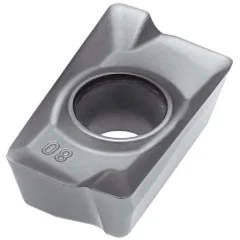
DCMT 11T308 turning insert – 55° diamond with positive geometry
| Technical data | |
|---|---|
| Side length l | 11.6 mm |
| Insert thickness s | 3.97 mm |
| Hole diameter d1 | 4.4 mm |
| Corner radius rε | 0.8 mm |
| ANSI code | DCMT 32.52 |

Cutting data for the DCMT 11T308 insert for steel and stainless steel
finishing, semi-finishing and roughing — ISO P and M groups
| Material | Finishing | Semi-finishing | Roughing | ||||||
|---|---|---|---|---|---|---|---|---|---|
| Vc [m/min] | Feed f [mm/rev] | ap [mm] | Vc [m/min] | Feed f [mm/rev] | ap [mm] | Vc [m/min] | Feed f [mm/rev] | ap [mm] | |
| PSteel | 120-225 | 0.04 | 0.08 | 105-220 | 0.08 | 0.35 | 100-200 | 0.15 | 2 |
| MStainless steel | 124-216 | 0.04 | 0.08 | 120-210 | 0.08 | 0.35 | 110-210 | 0.15 | 2 |
H6310 cemented carbide positive diamond insert – applications and design
single-sided 55° diamond with a hole, countersink and chip breaker
The DCMT 11T308 turning insert is a single-sided, diamond-shaped indexable insert made of H6310 grade cemented carbide, designed for turning steel and stainless steel. The D shape, a diamond with an acute 55° included angle, facilitates machining of contours, undercuts and profiles during longitudinal and copy turning. Positive geometry with a 7° clearance angle reduces cutting forces, allowing smooth operation on slender shafts and in hole boring. The countersunk hole secures the insert with a clamping screw, while the single-sided chip breaker controls chip flow and breaking at low and medium feed rates. Two 55° corners provide two cutting edges, and the nose radius rε 0.8 mm combines surface finish with cutting edge strength. The insert belongs to the DCMT 11T3 family, whose variants differ mainly in nose radius and machining application.
Key advantages of the H6310 cemented carbide insert
- Two cutting edges — a single-sided positive insert with two 55° corners; when one corner becomes dull, index the insert in its pocket without changing the holder.
- Grade H6310 for ISO groups P and M — general-purpose PVD-coated carbide: steel (P20-P40) and stainless steel (M20-M40), and occasionally cast iron.
- Positive 7° geometry — low cutting forces and reduced vibration on thin-walled and slender workpieces and in hole boring.
- The nose radius rε 0.8 mm provides a good surface finish in finishing and semi-finishing without changing the insert between operations.
- Dimensions according to ISO 1832: edge length 11.6 mm, IC 9.525 mm (3/8″), thickness 3.97 mm — fit holders with a 11 pocket.
- Tolerance class M provides repeatable edge positioning after indexing the insert, making it easier to maintain dimensions in production batches.
Applications and cutting data selection for the diamond-shaped insert
The DCMT 11T308 insert (also written without a space as dcmt11t308) is suitable for finishing and semi-finishing shafts, bushings and thin-walled workpieces made of structural steels and stainless steel. Calculate spindle speed using n = 1000·Vc/(π·D): for a shaft diameter of 40 mm at Vc = 200 m/min, the result is approximately 1592 rpm. For stainless steel, maintain a cutting speed of 124–216 m/min and a constant feed rate to reduce work hardening of the layer being cut. The sharp, positive shape and low cutting forces make this turning tool insert a good choice for internal boring with less rigid boring bars. The PVD coating improves edge resistance to abrasion and heat, while the single-sided chip breaker controls chips at feed rates of 0.04–0.15 mm/rev. Keep the depth of cut ap within 0.08–2 mm depending on the operation, from finishing to lighter roughing. Use ample coolant and rigid workpiece clamping for stable chip breaking and good surface quality. Indexable inserts made of H6310 grade cemented carbide are supplied by Korean brand Horn.
▲
Application limitation
Grade H6310 is not intended for steels hardened above 45 HRC — for turning hardened steel, select an insert with a cubic boron nitride cutting edge (CBN).
Rhombic insert designation decoder according to ISO 1832
how to read the DCMT 11T308 code — designation positions 1–7
Designation DCMT 11T308 according to the standard ISO 1832: 4 letters describe geometry and construction, 3 numeric codes describe dimensions. Each field has a number, an icon, and a brief description.
Compatible turning tools
holders with a 11 diamond pocket (SDHCR, SDJCR, SDNCN) — external and internal turning
SDHCR/L 1616 H1116×16 × 100 mmR right-hand
←L left-hand
→
←L left-hand
→
SDHCR/L 2020 K1120×20 × 125 mmR right-hand
←L left-hand
→
←L left-hand
→
SDHCR/L 2525 M1125×25 × 150 mmR right-hand
←L left-hand
→
←L left-hand
→
SDHCR/L 3232 P1132×32 × 170 mmR right-hand
←L left-hand
→
←L left-hand
→
SDJCR/L 1212 F1112×12 × 80 mmR right-hand
←L left-hand
→
←L left-hand
→
SDJCR/L 1616 H1116×16 × 100 mmR right-hand
←L left-hand
→
←L left-hand
→
SDJCR/L 2020 K1120×20 × 125 mmR right-hand
←L left-hand
→
←L left-hand
→
SDJCR/L 2525 M1125×25 × 150 mmR right-hand
←L left-hand
→
←L left-hand
→
SDJCR/L 3232 P1132×32 × 170 mmR right-hand
←L left-hand
→
←L left-hand
→
SDNCN 1212 F1112×12 × 80 mmR right-hand
←L left-hand
→
←L left-hand
→
SDNCN 1616 H1116×16 × 100 mmR right-hand
←L left-hand
→
←L left-hand
→
SDNCN 2020 K1120×20 × 125 mmR right-hand
←L left-hand
→
←L left-hand
→
SDNCN 2525 M1125×25 × 150 mmR right-hand
←L left-hand
→
←L left-hand
→
SDNCN 3232 P1132×32 × 170 mmR right-hand
←L left-hand
→
←L left-hand
→
S16P SDXCR/L-11Ø16 | Ømin 21 mm | L=170R right-hand
←L left-hand
→
←L left-hand
→
S20R SDXCR/L-11Ø20 | Ømin 25 mm | L=200R right-hand
←L left-hand
→
←L left-hand
→
S25S SDXCR/L-11Ø25 | Ømin 32 mm | L=250R right-hand
←L left-hand
→
←L left-hand
→
S32T SDXCR/L-11Ø32 | Ømin 40 mm | L=300R right-hand
←L left-hand
→
←L left-hand
→
S40U SDXCR/L-11Ø40 | Ømin 50 mm | L=350R right-hand
←L left-hand
→
←L left-hand
→
S16P SDPCR/L-11Ø16 | Ømin 21 mm | L=170R right-hand
←L left-hand
→
←L left-hand
→
S20R SDPCR/L-11Ø20 | Ømin 25 mm | L=200R right-hand
←L left-hand
→
←L left-hand
→
S25S SDPCR/L-11Ø25 | Ømin 32 mm | L=250R right-hand
←L left-hand
→
←L left-hand
→
S32T SDPCR/L-11Ø32 | Ømin 40 mm | L=300R right-hand
←L left-hand
→
←L left-hand
→
S40U SDPCR/L-11Ø40 | Ømin 50 mm | L=350R right-hand
←L left-hand
→
←L left-hand
→
S16P SD-CR/L-11Ø16 | Ømin 21 mm | L=170R right-hand
←L left-hand
→
←L left-hand
→
S20R SD-CR/L-11Ø20 | Ømin 25 mm | L=200R right-hand
←L left-hand
→
←L left-hand
→
S25S SD-CR/L-11Ø25 | Ømin 32 mm | L=250R right-hand
←L left-hand
→
←L left-hand
→
S32T SD-CR/L-11Ø32 | Ømin 40 mm | L=300R right-hand
←L left-hand
→
←L left-hand
→
S40U SD-CR/L-11Ø40 | Ømin 50 mm | L=350R right-hand
←L left-hand
→
←L left-hand
→
S16P SDQCR/L-11Ø16 | Ømin 21 mm | L=170R right-hand
←L left-hand
→
←L left-hand
→
S20R SDQCR/L-11Ø20 | Ømin 25 mm | L=200R right-hand
←L left-hand
→
←L left-hand
→
S25S SDQCR/L-11Ø25 | Ømin 32 mm | L=250R right-hand
←L left-hand
→
←L left-hand
→
S32T SDQCR/L-11Ø32 | Ømin 40 mm | L=300R right-hand
←L left-hand
→
←L left-hand
→
S40U SDQCR/L-11Ø40 | Ømin 50 mm | L=350R right-hand
←L left-hand
→
←L left-hand
→
S16P SDUCR/L-11Ø16 | Ømin 21 mm | L=170R right-hand
←L left-hand
→
←L left-hand
→
S20R SDUCR/L-11Ø20 | Ømin 25 mm | L=200R right-hand
←L left-hand
→
←L left-hand
→
S25S SDUCR/L-11Ø25 | Ømin 32 mm | L=250R right-hand
←L left-hand
→
←L left-hand
→
S32T SDUCR/L-11Ø32 | Ømin 40 mm | L=300R right-hand
←L left-hand
→
←L left-hand
→
S40U SDUCR/L-11Ø40 | Ømin 50 mm | L=350R right-hand
←L left-hand
→
←L left-hand
→
Frequently asked questions about the DCMT 11T308 insert
use, turning tool selection, and turning parameters
Two — the diamond has 2 corners of 55° each, and the positive geometry with a hole and countersink is single-sided, so only one side of the insert is used. When one corner becomes dull, simply index the insert in its pocket without changing the holder.
Holders with a 11 diamond-shaped pocket (IC 9.525 mm): for external turning SDHCR/L, SDJCR/L and SDNCN with cross sections of 12×12–32×32 mm; for internal turning, boring bars S16P–S40U with an SDXCR/L, SDPCR/L, SDQCR/L, SDUCR/L or SD-CR/L designation suffix. The full list is available in the compatible turning tools section.
Only in corner radius: 0.4 mm (11T304) is used for finishing at low feed rates with thin chips, while 0.8 mm (11T308) is a general-purpose option for finishing and semi-finishing. The other dimensions — IC 9.525 mm and thickness 3.97 mm — are identical.
Yes — grade H6310 covers group ISO M20-M40. Maintain a cutting speed of 124–216 m/min, a constant feed, and continuous emulsion cooling: austenitic steel conducts heat poorly and work-hardens when cutting is too slow.
Product accessories


Reviews
No customer reviews for the moment.
Shipping
All orders are delivered by courier company GLS. For orders exceeding 369 PLN gross shipping is FREE
| Courier GLS | Przelew24 / Prepayment | 14,76 zł gross | Delivery time 1 working day |
| Courier GLS | Cash on delivery | 17,26 zł gross | Lead time 1 working day |
Recommended for you


This website uses its own and third-party cookies to improve our services and show you advertising related to your preferences by analyzing your browsing habits. To give your consent to its use, press the Accept button.
Cookie preferences
Functional cookiesTechnical
Functional cookies are strictly necessary to provide the services of the shop, as well as for its proper functioning, so it is not possible to refuse their use. They allow the user to browse through our website and use the different options or services that exist on it.
Advertising Cookies
These are cookies that collect information about the advertisements shown to users of the website. They can be anonymous, if they only collect information about the advertising spaces shown without identifying the user, or personalised, if they collect personal information about the user of the shop by a third party, for the personalisation of these advertising spaces.
Analytics cookies
Collect information about the user's browsing experience in the shop, usually anonymously, although sometimes they also allow the user to be uniquely and unequivocally identified in order to obtain reports on the user's interests in the products or services offered by the shop.