





- 98% satisfied customers
- 72h delivery
- 30 dni na zwrot
Description
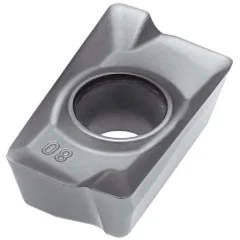
Internal inch threading insert 16 IR 11 W
Technical data for the full-profile insert for 11 threads per inch
| Technical data | |
|---|---|
| Designation | 16 IR 11 W MTA |
| Brand / part number | Horn / 124794 |
| Type | internal threading insert, right-hand |
| Profile | full, Whitworth, 55° angle |
| Pitch | 11 threads per inch (P = 2.309 mm) |
| Thread depth | 1.48 mm |
| Thread tolerance class | G: one class, no letter |
| Insert size | 16: edge 16 mm, IC 9.525 mm |
| Cutting edges | 3 |
| Tool holders | right-hand internal SIR, size 16, holes from Ø16 mm |
| Grade | MTA: submicron carbide, PVD TiAlN |


Threads per inch11

Profilefull 55°

Depth1.48 mm

Tool holdersSIR 16
Internal inch threading insert 16 IR 11 W turns the full internal thread profile at 11 threads per inch: flanks, rounded roots, and crests. It can cut G pipe threads from G 1 to G 6, as well as Whitworth BSF 7/8" threads in bores from Ø16 mm. It works in size 16 right-hand SIR boring bars. It has three corners for use in succession.
Full 55° profile – rounded thread root and crests
The insert finishes the thread crests in the same cycle
This insert
16 IR 11 W – full profile
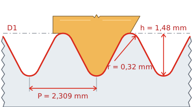
Crests rounded at diameter D1.
Comparison
Partial profile, e.g. 16 IR AG55
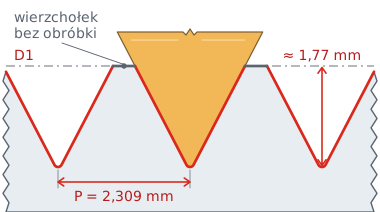
The crests remain as produced by boring the hole.
Axial section of a G 1 thread after the final pass. Gold highlights the insert; the red line shows the surfaces machined by the insert.
The Whitworth profile has a 55° angle and rounded thread roots and crests. The radius is 0.137 of the pitch, or approximately 0.32 mm at 11 threads per inch. The full-profile insert turns the flanks and both radii in the same cycle, producing the complete thread profile without separate bore machining.
For a G 1 thread, the bore diameter is 30.291–30.931 mm and the pitch diameter is 31.770–31.950 mm (ISO 228-1). Bore the hole slightly undersize beforehand. An oversized bore will leave the crests unmachined and the profile too shallow. Check the finished thread with a thread plug gauge or a screw.
This insert
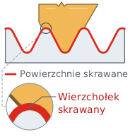
Full profile 16 IR 11 W
The insert cuts the flanks and the rounded root and crests of a thread with 11 threads per inch. The radii are formed in the same cycle as the flanks, ensuring a repeatable profile in production runs.
Choose for: production runs of threads with a single pitch.
Comparison
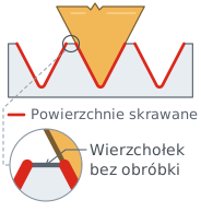
Partial profile, e.g. 16 IR AG55
The insert machines the flanks and root of the groove over a range of 48 to 8 threads per inch. It does not touch the crests: they retain the previously turned diameter.
Choose for: short runs and various pitches.
Threading with the 16 IR 11 W insert – passes, feed, and cutting data
Feed of 2.309 mm per revolution (11 threads per inch) and 7–14 progressively shallower passes
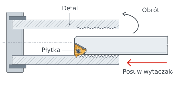
Schematic illustration: an insert in a right-hand SIR boring bar inside the workpiece bore. The insert is highlighted in gold.
One spindle revolution – 2.309 mm of feed
The workpiece rotates while the boring bar with the insert moves along the hole axis by 2.309 mm per spindle revolution. In a typical setup, the right-hand insert feeds toward the chuck and turns a right-hand thread. During the final passes, its side cutting edges trim the crests to the hole diameter.
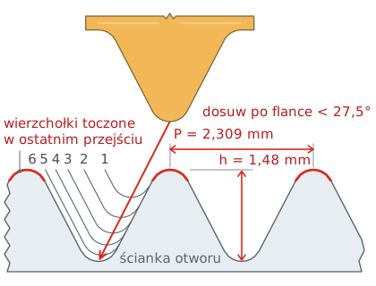
Schematic illustration of passes for a G 1 thread. The lines show successive cutting edge positions.
Successive passes to a depth of 1.48 mm
The insert reaches a depth of 1.48 mm in 7–14 passes (value interpolated from the manufacturer's table); use 10 as a starting point. The first pass removes the most material; the final pass removes 0.05–0.08 mm. Use flank infeed at an angle slightly less than 27.5°, which is half the thread angle: the insert then cuts mainly on one flank.
In a blind hole, make a relief groove at the end of the thread at least 2.5 mm wide and no shallower than the infeed depth.
Cutting speed for MTA grade
MTA grade is a submicron carbide with a PVD TiAlN coating for steel, stainless steel and cast iron. The speeds in the table apply to thread turning.
| Workpiece material | Cutting speed vc [m/min] |
|---|---|
| P Unalloyed steel, cast steel, free-cutting steel | 120–180 |
| P Low-alloy steel and cast steel (up to 5% alloying elements) | 80–130 |
| P High-alloy and tool steel | 60–80 |
| M Stainless steel and stainless cast steel | 90–130 |
| K Gray cast iron | 120–130 |
| K Ductile and malleable cast iron | 100–130 |
Spindle speed and feed for G 1
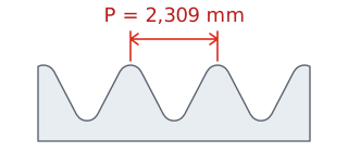
Pitch P is measured along the axis between corresponding points on adjacent thread turns.
For each spindle revolution, the insert advances by one pitch: fn = P = 2.309 mm/rev.
Example: G 1 in a bore in low-alloy steel, vc = 100 m/min
n = 1000 × vc / (π × d) = 1000 × 100 / (π × 33.249) ≈ 960 rpm
vf = n × P = 960 × 2.309
2217 mm/min
feed rate
d – thread diameter (33.249 mm), n – spindle speed, vc – cutting speed from the middle of the range in the table, vf – feed rate.
Calculate the helix angle β using tan β = P / (π × d), where P is the pitch and d is the thread diameter. For G 1: 2.309 / (π × 33.249) = 0.022, giving β ≈ 1.27°. Standard threading holder shims tilt the insert by 1–1.5°, so they do not need to be replaced for this thread.
Internal threads with 11 threads per inch – G 1 to G 6
One insert, all G pipe threads with this threads-per-inch value
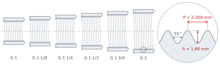
Hole diameters shown at the same scale. The tooth profile and thread depth are the same for each.
The number of threads per inch and the tooth profile are independent of diameter. The thread depth at 11 threads per inch is always 1.48 mm, for both G 1 and G 6. The bore in the workpiece determines the thread diameter, not the insert.
The 16 IR 11 W insert can cut any G pipe thread with 11 threads per inch to ISO 228-1, covering sizes from G 1 to G 6. Whitworth BSW and BSF threads with the same number of threads per inch have the same 55° profile.
| 55° thread type | Sizes with 11 threads per inch |
|---|---|
| G pipe threadsISO 228-1, sealing outside the thread | G 1G 1 1/8G 1 1/4G 1 1/2G 1 3/4G 2G 2 1/4G 2 1/2G 2 3/4G 3G 3 1/2G 4G 4 1/2G 5G 5 1/2G 6 |
| Whitworth BSFfine thread, B.S. 84 | 7/8" |
G 1 is highlighted in gold – the thread shown in the drawings and calculation example in this description.
Decoding the 16 IR 11 W designation – element by element
Size, cutting hand, threads-per-inch value, profile and grade in the insert designation, holder selection
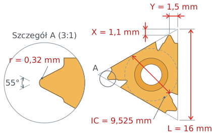
Dimensions according to catalogs for inserts of this standard. Enlarged corner detail.
16 IR 11 W insert dimensions
Size 16 indicates an edge length of 16 mm and an inscribed circle IC of 9.525 mm, or 3/8 inch; it is not the thread diameter. Dimensions X = 1.1 mm and Y = 1.5 mm specify the cutting tip position relative to the insert sides. The corner reproduces the Whitworth profile: a 55° angle and rounding radii of 0.137 times the pitch.
16

Insert size
Edge 16 mm, IC 9.525 mm.
I

Internal thread
Turning inside holes with a boring bar.
R

Right-hand version
SIR boring bar, feed toward the chuck.
11

Threads per inch
11 threads per inch, 2.309 mm pitch.
W

Whitworth profile
55° angle, full profile, rounded root.
MTA

Carbide grade
Submicron, PVD TiAlN, P20–P40 and K20–K30.
For 11 threads per inch and internal threads only
The insert profile matches only one pitch (number of threads per inch). At a different feed, the insert flanks will not align with the thread flanks, resulting in a distorted thread. A boring bar for size 16 inserts fits bores from Ø16 mm – this determines the minimum thread size.
Mount the threading insert in right-hand SIR boring bars for size 16 inserts, e.g. SIR 0013 M16, SIR 0016 P16 or SIR 0020 P16. A right-hand internal insert works only in a right-hand boring bar.
The 16 IR 11 W internal inch threading insert finishes an internal thread with 11 threads per inch, including the rounded crests. One insert can cut G pipe threads from G 1 to G 6, always at the same depth of 1.48 mm. It is suitable for production runs of fittings and valves with G threads.
16 IR 11 W – selection and application questions
Key information before selecting an insert
You can cut internal G pipe threads with 11 threads per inch: G 1 to G 6, as well as Whitworth threads with the same number of threads per inch.
Yes. The full profile forms the thread crests at the bore diameter, for example to 30.291–30.931 mm for G 1. Simply bore the hole slightly undersize beforehand.
The Whitworth profile depth is 0.6403 times the pitch, or 1.48 mm at 11 threads per inch (2.309 mm pitch). It is the same for every G thread with this threads-per-inch value.
Right-hand SIR boring bars for size 16 inserts, e.g. SIR 0013 M16 (holes from Ø16 mm), SIR 0016 P16 (from Ø19 mm), SIR 0020 P16 (from Ø24 mm) or SIR 0025 R16 (from Ø29 mm).
Usually 7 to 14 passes; use 10 as a starting point. The range is interpolated from the manufacturer's table for adjacent pitches.
Product accessories

Reviews
No customer reviews for the moment.
Shipping
All orders are delivered by courier company GLS. For orders exceeding 369 PLN gross shipping is FREE
| Courier GLS | Przelew24 / Prepayment | 14,76 zł gross | Delivery time 1 working day |
| Courier GLS | Cash on delivery | 17,26 zł gross | Lead time 1 working day |
Recommended for you


This website uses its own and third-party cookies to improve our services and show you advertising related to your preferences by analyzing your browsing habits. To give your consent to its use, press the Accept button.
Cookie preferences
Functional cookiesTechnical
Functional cookies are strictly necessary to provide the services of the shop, as well as for its proper functioning, so it is not possible to refuse their use. They allow the user to browse through our website and use the different options or services that exist on it.
Advertising Cookies
These are cookies that collect information about the advertisements shown to users of the website. They can be anonymous, if they only collect information about the advertising spaces shown without identifying the user, or personalised, if they collect personal information about the user of the shop by a third party, for the personalisation of these advertising spaces.
Analytics cookies
Collect information about the user's browsing experience in the shop, usually anonymously, although sometimes they also allow the user to be uniquely and unequivocally identified in order to obtain reports on the user's interests in the products or services offered by the shop.