





- 98% satisfied customers
- 72h delivery
- 30 dni na zwrot

Description
Angle to the axis45 degrees
Diameter range3–20 mm
InsertAPMT 1604
Length130 mm
Indexable countersink 3x20 mm – 45° chamfer mill for an APMT insert
Technical data and dimensions – 20 mm straight shank
| Technical data | |
|---|---|
| Cutting edge angle to the axis | 45° (90° cone) |
| Minimum diameter D2 | 3 mm |
| Maximum diameter D1 | 20 mm |
| Max. cutting depth | 8.5 mm |
| Overall length L | 130 mm |
| Shank diameter d | 20 mm, straight |
| Number of inserts Z | 1 |
| Insert | APMT 1604 |
| Manufacturer | Varel |
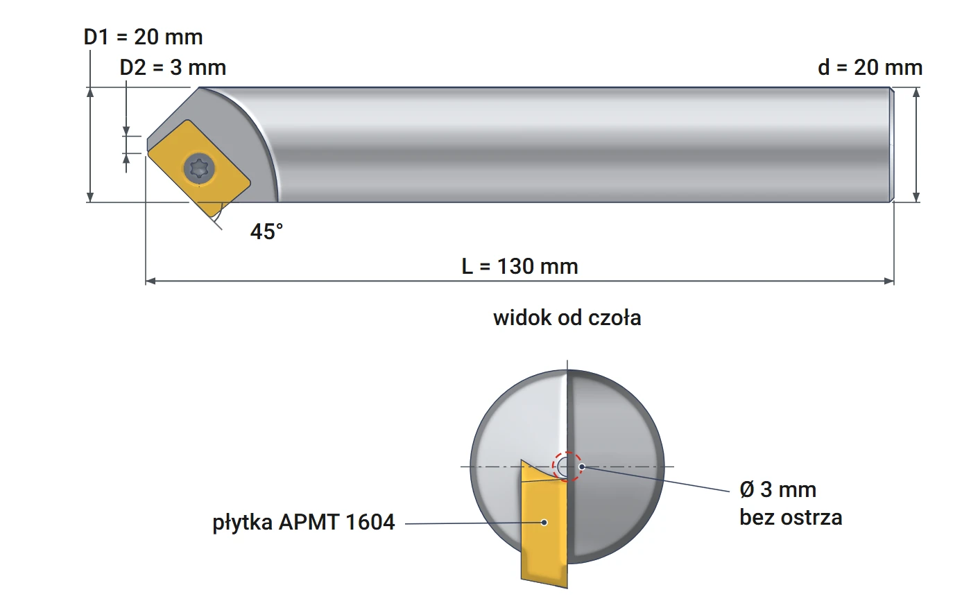
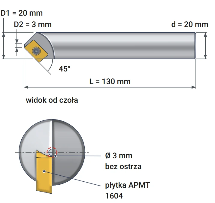
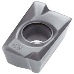
Indexable countersink 3x20 mm Varel cuts recesses for M3–M8 countersunk screw heads and chamfers hole edges. It cuts with one APMT 1604 insert over diameters from 3 to 20 mm. The insert has two cutting edges. A dull edge is replaced by indexing the insert by 180°, without sharpening the tool.
The 45° angle is measured between the insert edge and the tool axis. As it rotates, the insert sweeps a 90° cone. This matches the head angle of a metric countersunk screw. For every millimeter of plunge depth, the diameter increases by 2 mm. The entire feed is carried by one cutting edge, so a lower feed per revolution is selected. The 20 mm straight shank has the same diameter as the largest chamfer.
Applications – countersunk screw seat and slot chamfers
Operations with the 90° countersink
The same insert edges cut the screw head recess and the chamfer. The countersink also works as a 45° chamfer mill. Only the tool path and plunge depth change. The countersink machines holes and slots wider than 3 mm.
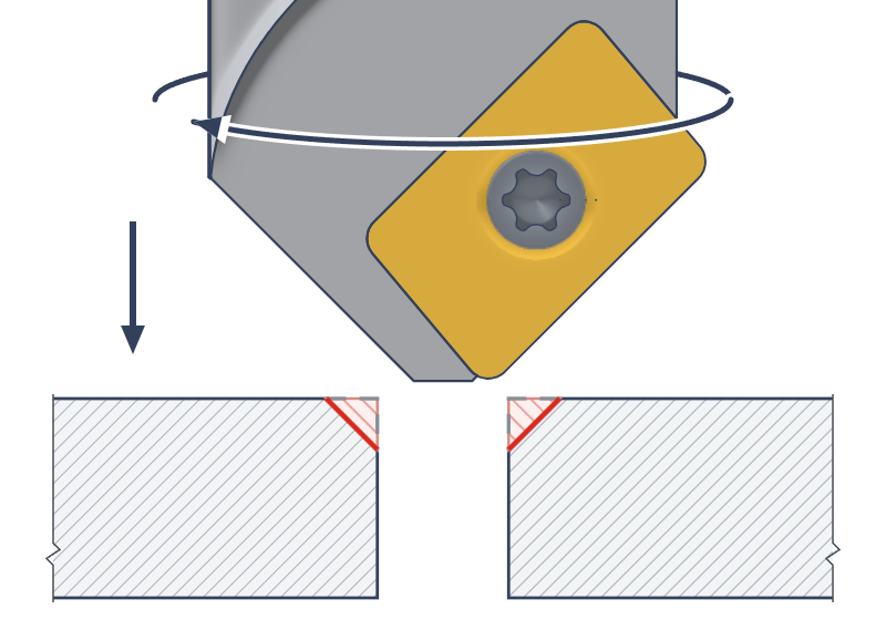
Countersunk screw seat
The insert sweeps a 90° cone, matching the screw head specified in DIN 7991. The countersink feeds axially into the clearance hole to the calculated depth. It accommodates M3, M4, M5, M6, and M8 heads with diameters from 6 to 16 mm. The head sits flush with the workpiece surface or 0.1 mm below it.
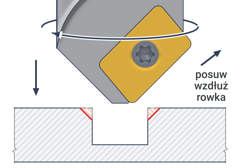
Chamfer on both slot edges
The tool is guided along the center of a slot from 3 to 20 mm wide. The insert chamfers both upper edges in a single pass. Chamfer width is set by the plunge depth. This method is used to chamfer keyway and guideway edges.
Screw head recess – selection and depth
Which screws fit and how deep to plunge
The countersink cuts from 3 mm to 20 mm in diameter. A complete recess requires two conditions. The clearance hole must be larger than 3 mm. The screw head must be less than 20 mm in diameter.
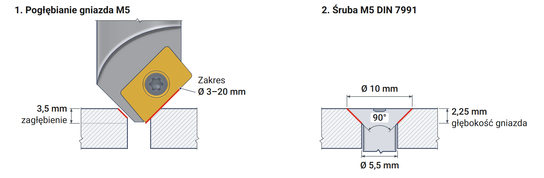
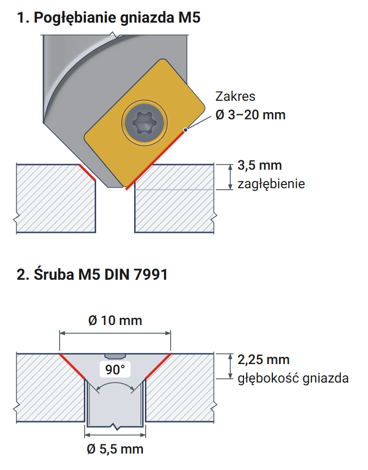
Calculator: Z-axis plunge depth for recess diameter
With a 90° cone, each millimeter of downward travel adds 2 mm to the diameter. Plunge depth is measured from the workpiece surface to the insert corners at a diameter of 3 mm. Plunge depth = (recess diameter − 3 mm) ÷ 2, e.g., (10 − 3) ÷ 2 = 3.5 mm for an M5 head.
▲
Clearance hole wider than 3 mm
The countersink cuts from a diameter of 3 mm. In a clearance hole wider than 3 mm, e.g., 3.4 mm for M3, the recess is complete and the head seats fully.
APMT 1604 insert – two edges and indexing
Rectangular 85° insert to ISO 1832
A indicates a 85° parallelogram, in practice a rectangular insert. The insert has two cutting edges, one on each longer side. P indicates a 11° clearance angle, M the tolerance class, and T a screw hole and a chip breaker on one side. 16 indicates an edge length of approx. 16 mm, and 04 a thickness of 4.76 mm.
A 3–20 mm chamfer uses approx. 12 mm of the cutting edge, so one edge covers the entire range. The countersink is sold without inserts.
Changing edges step by step
1Loosening the screw
Insert: removed
2Indexing the insert
Rotation: 180°
3Cleaning the insert seat
Chips: removed
4Tightening the screw
Insert: seated
✓Test recess
Check: with the screw head
With one insert, each indexing operation provides a fresh edge across the entire 3–20 mm range. A chip under the insert shifts the cutting edge and changes the recess diameter, so the insert seat must be cleaned before installation.
Cutting data – starting values
Cutting speed and feed per tooth – conservative ranges
The values are based on conservative milling ranges with a 45° entering angle according to ISO 513. Start at the lower limit and increase the values while monitoring the chips and spindle sound.
| Workpiece material | Cutting speed vc [m/min] | Feed per tooth fz [mm] |
|---|---|---|
| P Structural and alloy steel | 150–220 | 0.10–0.22 |
| M Stainless steel | 80–140 | 0.08–0.18 |
| K Gray cast iron | 180–300 | 0.10–0.28 |
Calculating spindle speed and feed rate – M5 recess in steel
Spindle speed is calculated for the largest diameter engaged in the material, here the 10 mm head. Spindle speed = 1000 × cutting speed 150 m/min ÷ (3.14 × diameter 10 mm) ≈ 4770 rpm. Feed rate = feed per tooth 0.10 mm × 1 insert × 4770 rpm ≈ 470 mm/min. These two values are entered in the machine tool program.
Higher spindle speeds and lighter pressure work well for countersinking. Low speeds with heavy pressure cause vibration. When machining stainless steel, coolant protects the hole edge from overheating.
Indexable countersink 3x20 mm Varel cuts 90° recesses for M3, M4, M5, M6, and M8 heads. It also chamfers holes wider than 3 mm and slot edges. It cuts with one APMT 1604 insert over diameters from 3 to 20 mm. The 20 mm straight shank and 130 mm length allow it to be mounted in a collet chuck.
Questions about the 3x20 indexable countersink
Recess, inserts, depth, CNC program
For 90° countersunk screws to DIN 7991: M3, M4, M5, M6, and M8. Their head diameters are 6, 8, 10, 12, and 16 mm, and their clearance hole diameters are 3.4; 4.5; 5.5; 6.6, and 9 mm. The calculator above gives the plunge depth for each of these screws.
APMT 1604 inserts – rectangular, 85°, with a screw hole. Each has two cutting edges.
One APMT 1604 insert. The insert has two edges, providing two usable edge positions.
Enter a 90° countersink with a tip diameter of 3 mm in the tool table. Measure the tool height to the insert corners. Plunge depth = (head diameter − 3 mm) ÷ 2, plus approx. 0.1 mm.
Product accessories


Carbide insert APKT 160408 PDER XM H6310 Horn
Reference: 10358 In stock > 10 items
€4.08
€5.02 brutto
Reviews
No customer reviews for the moment.
Shipping
All orders are delivered by courier company GLS. For orders exceeding 369 PLN gross shipping is FREE
| Courier GLS | Przelew24 / Prepayment | 14,76 zł gross | Delivery time 1 working day |
| Courier GLS | Cash on delivery | 17,26 zł gross | Lead time 1 working day |
Recommended for you


This website uses its own and third-party cookies to improve our services and show you advertising related to your preferences by analyzing your browsing habits. To give your consent to its use, press the Accept button.
Cookie preferences
Functional cookiesTechnical
Functional cookies are strictly necessary to provide the services of the shop, as well as for its proper functioning, so it is not possible to refuse their use. They allow the user to browse through our website and use the different options or services that exist on it.
Advertising Cookies
These are cookies that collect information about the advertisements shown to users of the website. They can be anonymous, if they only collect information about the advertising spaces shown without identifying the user, or personalised, if they collect personal information about the user of the shop by a third party, for the personalisation of these advertising spaces.
Analytics cookies
Collect information about the user's browsing experience in the shop, usually anonymously, although sometimes they also allow the user to be uniquely and unequivocally identified in order to obtain reports on the user's interests in the products or services offered by the shop.