




- 98% satisfied customers
- 72h delivery
- 30 dni na zwrot

Description
CUTTING WIDTH2 mm
CUTTING DEPTH T MAX15 mm
MAX. BAR DIAMETERØ30 mm
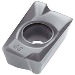
INSERT · 2 EDGESMGMN 200
Parting tool 25X25 2 mm T15 Varel
Technical data for the holder for Korloy MGMN 200 inserts
| Technical data | |
|---|---|
| Designation | MGEHR 2525-2 |
| Type | holder for parting and external grooving |
| Shank height h | 25 mm |
| Shank width B | 25 mm |
| Overall length L | 150 mm |
| Dimension S (to the insert edge) | 25.3 mm |
| Cutting depth T max | 15 mm |
| Max. parting diameter D max | Ø30 mm |
| Insert pocket | MGMN 200 (width 2 mm) |
| Hand | R – right-hand |

MGEHR 2525-2 – design and clamping of the 2 mm insert
What this tool can do, screw clamping and a double-edged insert
For parting off workpieces from bar stock and cutting external grooves, use 2 mm parting tool MGEHR 2525-2 by Varel. The holder accepts a double-edged MGMN 200 carbide insert with a width of 2 mm. The insert is clamped from above by the flexible lip of the head, tightened with a screw. You can replace it without removing the tool from the tool post.
The insert edge projects 0.3 mm beyond the side of the shank (S = 25.3 mm with B = 25 mm). When cutting close to the chuck, only the cutting edge engages; the shank does not rub against the workpiece face. The 25x25 mm shank, 150 mm long, provides the rigidity required by a narrow cutting edge in an enclosed groove.
The MGMN 200 insert is double-edged: when one edge becomes dull, rotate it by 180° and cut with the other end.
The head forms a thin blade 15 mm long, which determines the cutting depth T max. Behind the blade, the head widens to the full shank width and can no longer enter the 2 mm groove. This sets the limit: the tool parts off bars up to Ø30 mm, or twice T max.
Parting and grooving with the MGEHR 2525-2 tool – typical operations
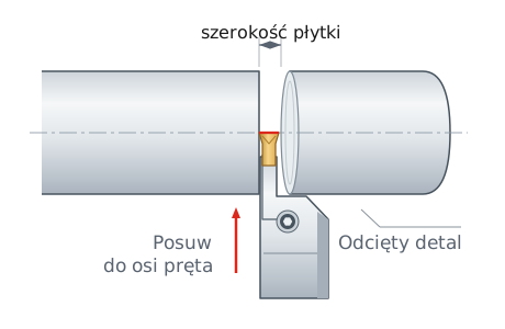
Parting – cutting a part off a bar
The blade enters the bar all the way to the axis and the part separates. Bars up to Ø30 mm, a 2 mm kerf, and material loss limited to the insert width.
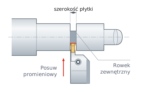
Cutting external grooves
A 2 mm groove between shaft shoulders or a retaining ring groove at the end of a journal, up to 15 mm deep. Cut wider grooves with several adjacent passes.

Screw clamping from above
The screw pulls the head's flexible lip down against the insert. The insert can be replaced without removing the tool from the tool post.

Double-edged insert
MGMN 200 has a cutting edge at both ends. One edge dull? Rotate the insert by 180° and use the other.

Material loss: 2 mm
Each parting cut turns only 2 mm of bar into chips. For 100 parts, this consumes 10 cm less bar than a tool with a 3 mm insert.
Dimensions and cutting reach – dimensional drawing
Side view and top view
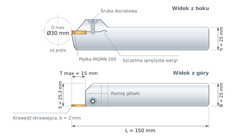

HEIGHT h
25 mm

WIDTH B
25 mm

LENGTH L
150 mm

DIMENSION S
25.3 mm
T max is measured from the insert tip to the head shoulder. A groove shallower than 15 mm can also be cut in a bar larger than Ø30 mm.
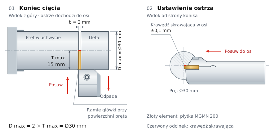
The left panel of the diagram shows the end of the cut: the insert tip is on the bar axis, and the head shoulder touches its surface. The right panel shows cutting edge height: set the edge on the centerline to within ±0.1 mm. Below the centerline, a pip remains; above the centerline, the cutting edge rubs against the material.
Decoding the MGEHR 2525-2 designation
The four parts of the MGT system designation, read from the left
Designation: MGEHR 2525-2
MGEH
Element 1
holder type
holder type
For parting
MGEH
MGEH
External grooving and parting holder for the MGT insert system, with screw-operated top clamping.
R
Element 2
hand
hand
Right-hand
R
R
Standard configuration with the workpiece clamped in the chuck to the left of the tool. The mirror-image version is designated MGEHL.
2525
Element 3
shank
shank
25x25 mm
2525
2525
The first two digits indicate height h, and the next two indicate width B. Fits a tool post for 25 mm tools.
-2
Element 4
insert width
insert width
2 mm
-2
-2
The number after the hyphen is the insert width in millimeters. The pocket accepts MGMN 200 inserts, and T max is 15 mm (bars up to Ø30 mm).
MGT system catalog convention, not ISO 5608 · dimensions: h 25 · B 25 · L 150 · S 25.3 mm
Parting data – speeds and feeds for a 2 mm insert
Starting values with coolant; refer to the insert grade data sheet for definitive data
The values apply to coated MGMN 200 inserts used with coolant. Use the higher speeds with rigid clamping and short overhang.
| Workpiece material | Vc [m/min] | fn [mm/rev] |
|---|---|---|
| PCarbon steel | 150–200 | 0.05–0.12 |
| PAlloy steel | 130–180 | 0.05–0.12 |
| PHardened steel | 90–130 | 0.05–0.10 |
| MStainless steel | 130–160 | 0.05–0.12 |
| KCast iron | 150–210 | 0.05–0.12 |
Starting spindle speed: n = (1000 × Vc) / (π × D). For a Ø30 mm carbon steel bar at Vc = 180 m/min: n = (1000 × 180) / (3.14 × 30) ≈ 1910 rpm. At constant spindle speed, the cutting speed decreases to zero at the centerline, so enable constant surface speed (G96) with a spindle speed limit on a CNC lathe.
▲
Operating limitations
Do not part off bars larger than Ø30 mm: the shoulder of the head will contact the material before the cutting edge reaches the centerline. Keep overhang from the tool post as short as possible. Over the final 2 mm before the centerline, reduce the feed by as much as 75% and direct coolant straight into the cut.
Installing the MGMN 200 insert in 3 steps
1Loosen
the clamping screw by 2–3 turns
2Seat
clean the pocket, slide the insert in until fully seated
3Tighten
and check that the cutting edge is on the lathe centerline ±0.1 mm
✓Ready
parting off bars up to Ø30 mm
Cutting insert not included
COMPATIBLE WITH:
| ✓ | MGMN 200 parting inserts (Korloy MGT system) – width 2.0 mm, length 16 mm, height 3.5 mm |
| ✓ | Left-hand MGEHL 2525-2 version with the same dimensions |
| ✓ | Other sizes in the -2 series available: MGEHR 1616-2 (T max 15 mm), MGEHR 2020-2 (T max 15 mm) |
Varel parting tools and boring bars for MGMN 200 inserts
MGEHR/L 1616-216x16 mm | L 100 mm | T max 15 mm | Ø30 mmR right-hand
←L left-hand
→
←L left-hand
→
MGEHR/L 2020-220x20 mm | L 125 mm | T max 15 mm | Ø30 mmR right-hand
←L left-hand
→
←L left-hand
→
MGIVR/L 2520-2Ø20 mm | Ømin 25 mm | L 150 mm | T max 6 mmR right-hand
←L left-hand
→
←L left-hand
→
Inserts from other grooving systems (DGN, GTN, KGM) require different seats and do not fit this holder. The 2 mm MGEHR 2525-2 parting tool parts off workpieces from bar stock up to Ø30 mm and cuts external grooves with a width of 2 mm. The MGMN insert in tolerance class M maintains the cutting edge width within ±0.05 mm. Groove depth is limited by T max = 15 mm. On automatic and CNC lathes in series production, it parts off workpieces from bar stock in every cycle.
Frequently asked questions
An MGMN 200 parting insert (Korloy MGT system) with a width of 2.0 mm, length of 16 mm and height of 3.5 mm. It is double-ended, so each insert provides two cutting edges. DGN, GTN and KGM inserts do not fit this pocket.
Ø30 mm, or twice the cutting depth T max = 15 mm. Larger bars require a holder with a greater cutting depth T max. Grooves shallower than 15 mm can also be cut on larger diameters.
Yes. The holder cuts external grooves 2 mm wide and up to 15 mm deep. An insert with -M geometry also allows turning with the side of the insert, but with a depth of cut of up to 0.8 × 2 mm = 1.6 mm per pass.
A pip remains when the cutting edge is not on the lathe centerline. Set it within ±0.1 mm and check that the insert is fully seated in the pocket. Over the final 2 mm before the centerline, reduce the feed by as much as 75%.
Product accessories


Reviews
No customer reviews for the moment.
Shipping
All orders are delivered by courier company GLS. For orders exceeding 369 PLN gross shipping is FREE
| Courier GLS | Przelew24 / Prepayment | 14,76 zł gross | Delivery time 1 working day |
| Courier GLS | Cash on delivery | 17,26 zł gross | Lead time 1 working day |
Recommended for you


This website uses its own and third-party cookies to improve our services and show you advertising related to your preferences by analyzing your browsing habits. To give your consent to its use, press the Accept button.
Cookie preferences
Functional cookiesTechnical
Functional cookies are strictly necessary to provide the services of the shop, as well as for its proper functioning, so it is not possible to refuse their use. They allow the user to browse through our website and use the different options or services that exist on it.
Advertising Cookies
These are cookies that collect information about the advertisements shown to users of the website. They can be anonymous, if they only collect information about the advertising spaces shown without identifying the user, or personalised, if they collect personal information about the user of the shop by a third party, for the personalisation of these advertising spaces.
Analytics cookies
Collect information about the user's browsing experience in the shop, usually anonymously, although sometimes they also allow the user to be uniquely and unequivocally identified in order to obtain reports on the user's interests in the products or services offered by the shop.