




- 98% satisfied customers
- 72h delivery
- 30 dni na zwrot

Description
External threading turning tool SER 10X10-11 Varel
Right-hand tool holder SER-1010H11 for 11 ER inserts
| Technical data | |
|---|---|
| Manufacturer designation | SER-1010H11 |
| Machining operation | External threading |
| Design | Right-hand (R) |
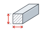
| Shank cross section | 10x10 mm |
| Overall length | 100 mm |
| Distance from cutting edge to back of shank | 12 mm |
| Insert family | 11 ER |
| Thread types with the appropriate insert | Metric M – 60° Parallel pipe G – 55° Unified UN – 60° |
| Metric pitch range | 0.5–2.0 mm Depending on the selected 11 ER insert |

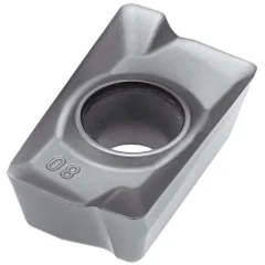
The photo shows the SER-2020K16 tool holder from this family.
The table data applies to the SER-1010H11 variant.
The insert shown in the photo is not included with the turning tool.

SER-1010H11 – external thread turning in practice
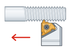
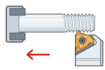
The workpiece rotates while the cutting edge moves along its axis
External threading turning tool SER 10X10-11 Varel is a right-hand tool holder for turning threads on shafts, journals, and bushings. The 10x10 mm shank is clamped in a suitable lathe tool post. With a suitable 11 ER insert, you can cut metric M and inch UN threads with a 60° profile, as well as G parallel pipe threads with a 55° profile.
The metric pitch range is 0.5–2.0 mm, depending on the selected insert. For inch G and UN threads, match the insert to the profile and threads per inch (TPI). Example: a G 1/4 thread has 19 threads per inch and falls within the range of the 11 ER A55 insert (48–16 threads per inch). This is an indexable turning tool: when the cutting edge wears out, only the insert is replaced, while the body is retained.
The thread diameter is determined by the shaft being machined, not the tool holder. The same 11 ER A60 insert can therefore cut, for example, M6 x1 and M24x1. This is why a threading tool replaces a set of dies for fine threads and large diameters.
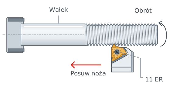
Schematic diagram. Typical setup of a right-hand turning tool in front of the lathe axis.
How does an external threading tool work?
The insert deepens the same profile with each successive pass. The feed remains synchronized with spindle rotation. For a single-start thread, tool travel per revolution equals the thread pitch.
In a typical setup, a right-hand turning tool cuts toward the lathe chuck. The R symbol itself identifies the holder design. The hand of the resulting thread also depends on the tool setup, spindle rotation and feed direction.
11 ER inserts – selecting the thread profile and pitch
One holder, different tasks with the appropriate insert
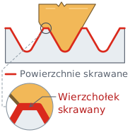
Full profile 11 ER ISO
A full-profile insert, such as 11 ER 1.5 ISO, is designed for a specific pitch. It machines the thread flanks, root and crest. A different pitch requires the appropriate insert version.
Example: metric profile, 1.5 mm pitch.
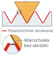
Partial profile 11 ER A60
A partial-profile insert, such as 11 ER A60, covers pitches of 0.5–1.5 mm (48–16 threads per inch). It does not finish the thread crests. The outside diameter of the part must be prepared beforehand with a suitable tool.
Selection: profile, pitch range and insert grade.
Choose a full-profile insert for production runs of a single thread. The crest is formed together with the flanks, without a separate operation, and the profile is repeatable. An A60 insert with a 60° profile or an A55 insert with a 55° profile covers several pitches, making it useful for short runs and individual parts. The crest then depends on the previously bored diameter, so profile control is less precise.

The final “11” indicates the insert size, not the diameter of the thread being cut. The thread profile and pitch depend on the selected 11 ER insert. 16 ER and 11 IR inserts are not direct substitutes for each other.
Threading with a turning tool on a lathe – setup and feed
Short overhang, correct cutting edge height and synchronized motion
Set the cutting tip at spindle center height. Check the alignment of the insert profile relative to the workpiece axis. Minimize shank overhang to reduce susceptibility to vibration. Remove chips from the pocket and support surfaces before mounting.
Select the cutting speed and number of passes according to the insert, material and clamping rigidity. The SER body alone does not determine cutting data for steel, stainless steel or aluminum.
The external threading turning tool SER 10X10-11 Varel requires a tool post for a 10x10 mm shank that allows the cutting edge height to be set correctly. When selecting it, also check the clearance around the workpiece. The overall length of 100 mm describes the body, not the permissible working overhang. Inspect the final thread size according to the requirements of the part drawing.
Feed for a 1.5 mm pitch
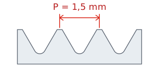
Pitch P is measured along the axis between corresponding points on adjacent thread turns.
For a single-start thread, the tool moves axially by 1.5 mm for each spindle revolution.
Feed per revolution:
fn = P = 1.5 mm/rev.
Example: spindle speed n = 400 rpm
vf = n × P = 400 × 1.5
600 mm/min
Feed rate
400 rpm is a calculation example, not recommended cutting data. The threading cycle requires the feed to be synchronized with the spindle.
Thread turning with a turning tool – approach, cutting pass and retraction
Each pass uses the same four movements, going slightly deeper each time
The thread is formed in several passes. In each pass, the tool follows the same cycle of four movements, and the 11 ER insert cuts slightly deeper each time until the profile reaches full depth. The diagram shows one pass in a typical right-hand SER turning tool setup.
Single-pass cycle
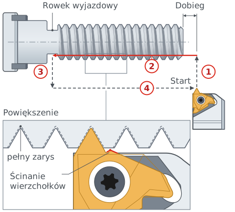
Schematic diagram, top view. Red line – cutting movement, the insert is cutting. Dashed lines – rapid movements without cutting.
1
Approach
The tool moves from the starting point in front of the shaft end face and feeds in perpendicular to the axis to the depth of this pass. This is a rapid movement without cutting.
2
Cutting pass
The insert cuts while moving along the axis toward the chuck. For each spindle revolution, the tool advances by the thread pitch P, for example 1.5 mm.
3
Retraction
At the end of the thread, the tool rapidly retracts from the shaft. At a workpiece shoulder, it does this in the thread relief groove before reaching the shoulder face.
4
Return
The retracted tool rapidly returns to the starting point. It begins the next pass with a slightly deeper infeed.
Set the starting point in front of the shaft end face. The insert then enters the material with the feed already equal to the pitch. Metric thread depth is approximately 0.61 × P, or approximately 0.92 mm for a pitch of 1.5 mm. At a workpiece shoulder, machine a thread relief groove at least 1.05 × P wide, or approximately 1.6 mm, and at least as deep as the thread.
Tool infeed and number of passes in thread turning
The infeed direction determines which insert edge cuts
Infeed is the movement that takes the insert deeper on the next pass. Its direction determines which insert edge cuts and how the chip flows. In the diagrams, red lines show successive positions of the insert tip, and the arrow shows the infeed direction. The numbers 1–5 and progressively darker bands indicate successive passes, or the layers of material removed in each pass. The bold line shows the insert edge that is cutting.
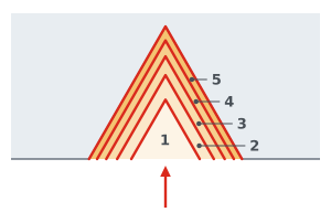
Radial infeed
The insert feeds straight toward the axis and cuts with both edges. This is the simplest method. It works well for fine pitches, short-chipping materials and hardened materials.
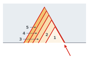
Modified flank infeed
The tool moves diagonally along the flank, or side of the profile, at an angle a few degrees less than 30°. One edge does most of the cutting, while the other does not rub against the thread flank. Manufacturers recommend this method as the first choice for most threads.
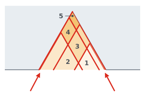
Alternating flank infeed
The tool alternately moves along each flank of the profile, so both edges wear evenly. This method helps with coarse pitches and long-chipping materials. It requires a program that is not available on every lathe.
Select the number of passes according to the pitch and material. For a pitch of 1.5 mm, insert manufacturers' catalogs specify 5–11 or 6–10 passes; harder materials require more passes. The first pass is the deepest, and each subsequent pass is shallower, keeping the chip cross section similar. The final pass should not be shallower than approximately 0.05 mm, or the edge will start rubbing instead of cutting.
SER 10X10-11 – selection and application questions
Key information before selecting a holder
The tool holder accepts right-hand external threading inserts from the 11 ER family. These include full-profile inserts, such as 11 ER 1.5 ISO or 11 ER 19 W, and partial-profile inserts, such as 11 ER A60 and 11 ER A55. Select the profile, pitch, and grade suitable for the application.
Up to 2 mm for metric threads, for example M14 x2 with a 11 ER 2.0 ISO insert. The 11 ER A60 and 11 ER A55 inserts cover pitches of 0.5–1.5 mm, or 48–16 threads per inch.
For G parallel pipe threads from G 1/16 to G 7/8, with 28, 19, and 14 threads per inch. The 11 ER A55 insert covers 48–16 threads per inch, corresponding to G 1/16–G 3/8. Sizes G 1/2–G 7/8 can be cut with a 11 ER 14 W full-profile insert.
With a 11 ER A60 insert, you can cut metric threads with pitches of 0.5–1.5 mm, such as M3 x0.5, M4 x0.7, and M6 x1. The thread diameter is determined by the shaft being machined, so the same turning tool can also cut M10 x1.5.
Product accessories


Reviews
No customer reviews for the moment.
Shipping
All orders are delivered by courier company GLS. For orders exceeding 369 PLN gross shipping is FREE
| Courier GLS | Przelew24 / Prepayment | 14,76 zł gross | Delivery time 1 working day |
| Courier GLS | Cash on delivery | 17,26 zł gross | Lead time 1 working day |
Recommended for you


This website uses its own and third-party cookies to improve our services and show you advertising related to your preferences by analyzing your browsing habits. To give your consent to its use, press the Accept button.
Cookie preferences
Functional cookiesTechnical
Functional cookies are strictly necessary to provide the services of the shop, as well as for its proper functioning, so it is not possible to refuse their use. They allow the user to browse through our website and use the different options or services that exist on it.
Advertising Cookies
These are cookies that collect information about the advertisements shown to users of the website. They can be anonymous, if they only collect information about the advertising spaces shown without identifying the user, or personalised, if they collect personal information about the user of the shop by a third party, for the personalisation of these advertising spaces.
Analytics cookies
Collect information about the user's browsing experience in the shop, usually anonymously, although sometimes they also allow the user to be uniquely and unequivocally identified in order to obtain reports on the user's interests in the products or services offered by the shop.