 Polski





- 98% satisfied customers
- 72h delivery
- 30 dni na zwrot
Description
Ø20 mm indexable end mill for Ø10 mm round inserts – Smoxh RD1003
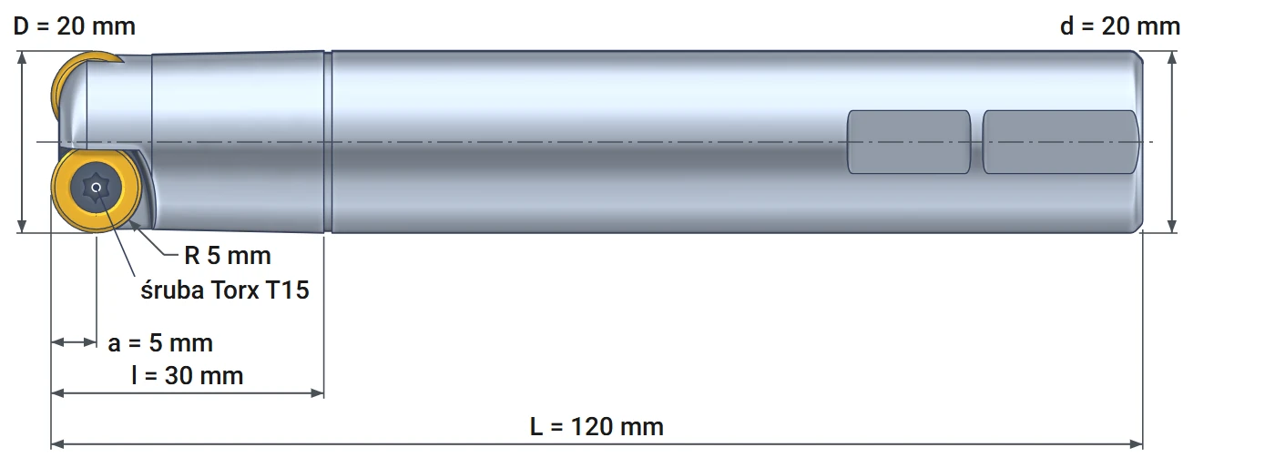
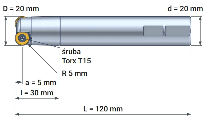
Technical data and dimensions – 20 mm Weldon shank, two RDMW 1003 inserts
| Technical data | |
|---|---|
| Cutter diameter D | 20 mm |
| Shank diameter d | 20 mm, Weldon |
| Max. depth of cut a | 5 mm |
| Flute length l | 30 mm |
| Overall length L | 120 mm |
| Number of inserts Z | 2 |
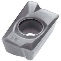
| Inserts | round RD.. 1003 (Ø 10 mm), e.g., RDMW 1003 |
| Coolant supply | external |
| Insert screw | M3.5x8, Torx T15, 2.7 N·m |
| Manufacturer | Smoxh, Turkey (SM13230) |
Diameter20 mm
Depth of cutup to 5 mm
Inserts2 × RDMW 1003
Overall length120 mm
Ø20 mm indexable end mill for Ø10 mm round inserts Smoxh RD1003 is a copy milling cutter with two inserts. It machines flat surfaces, steps, slots, pockets, holes and 3D shapes. The round edge has no corner that could chip. Each insert can be indexed several times before replacement. The 20 mm Weldon shank has a flat for the holder screw, preventing the cutter from rotating or pulling out.
Round insert – angle and chip thickness increase with depth
Why a round-insert cutter can handle a higher feed rate
A rectangular insert always cuts at the same angle. A round insert cuts at an angle that depends on the depth of cut. At a shallow depth, only the bottom of the circle engages, producing a thin chip. Cutting force is then low, and the cutter does not vibrate even with a long overhang.
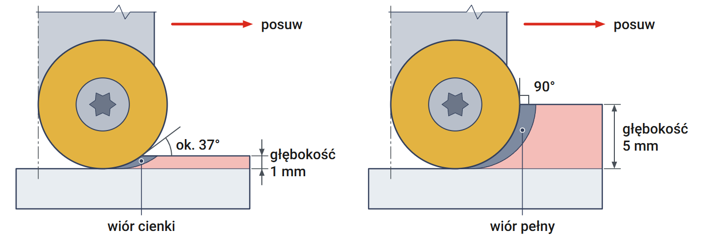
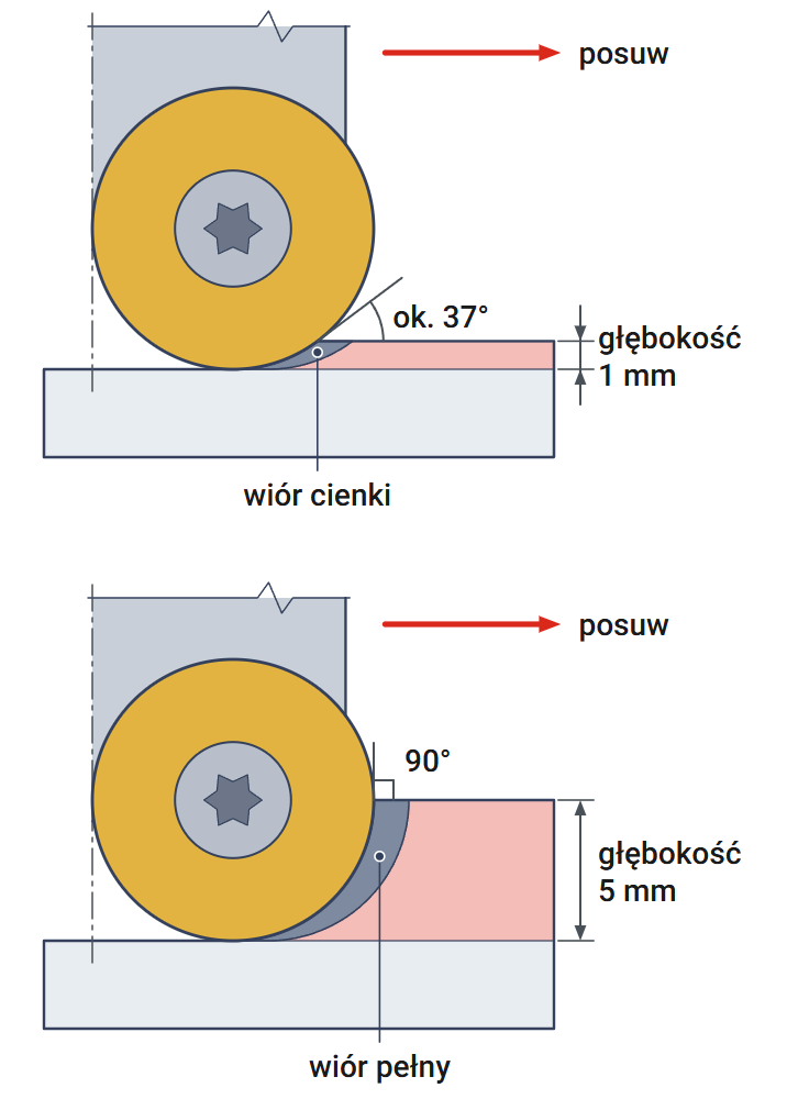
The drawing shows a Ø 10 mm insert at two depths. At 1 mm, the edge contacts the material at an angle of approximately 37°. At 5 mm, the full depth, the angle reaches 90°, as with a shoulder mill. Calculate the angle as follows: subtract the depth from the insert radius of 5 mm and divide by 5 mm. For 1 mm, this gives 4 ÷ 5 = 0.8, and the angle with a cosine of 0.8 is approximately 37°. The smaller the angle, the thinner the chip at the same feed rate.
A thinner chip allows a higher feed rate. At a depth of 1 mm, the feed per tooth can be approximately 1.7 times that of a 90° cutter. Chip thickness and insert load remain the same. Shallow, fast passes are therefore the most productive way to use this cutter.
Six operations with one cutter – from flat surfaces to 3D shapes
Face milling, step, slot, pocket, hole, contoured surface
Smoxh identifies this cutter with six operation pictograms. The drawings illustrate these operations with cutter movement and material removal. All result from one feature: the insert is a circle with a radius of 5 mm. The bottom therefore meets the wall with a radius rather than a sharp corner.
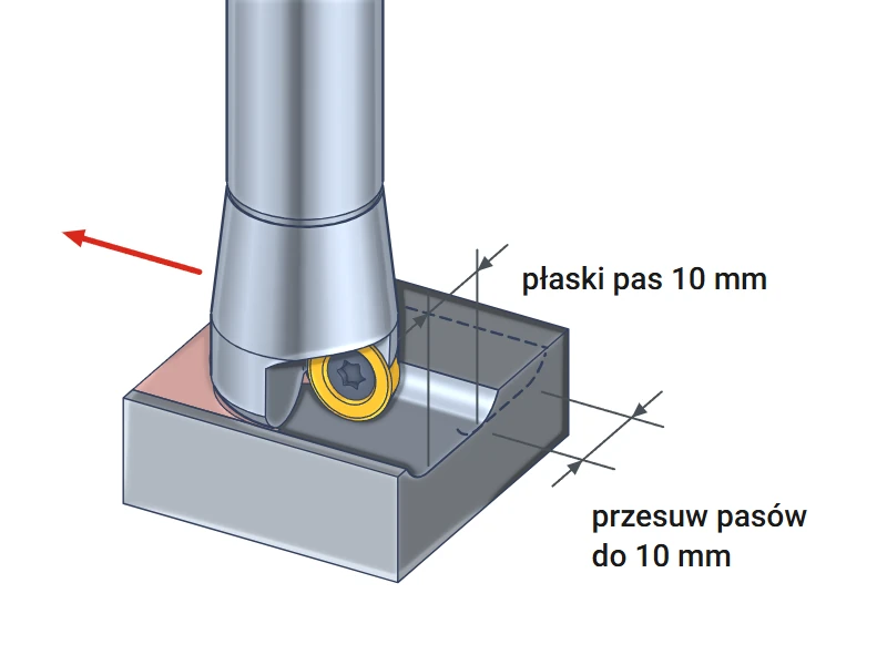
Face milling
Feed the cutter across the workpiece at a shallow depth. A flat bottom forms beneath the lowest point of the inserts in a strip 10 mm wide. Use a stepover of no more than 10 mm for successive passes. This removes a riser, scale or the face of a casting.
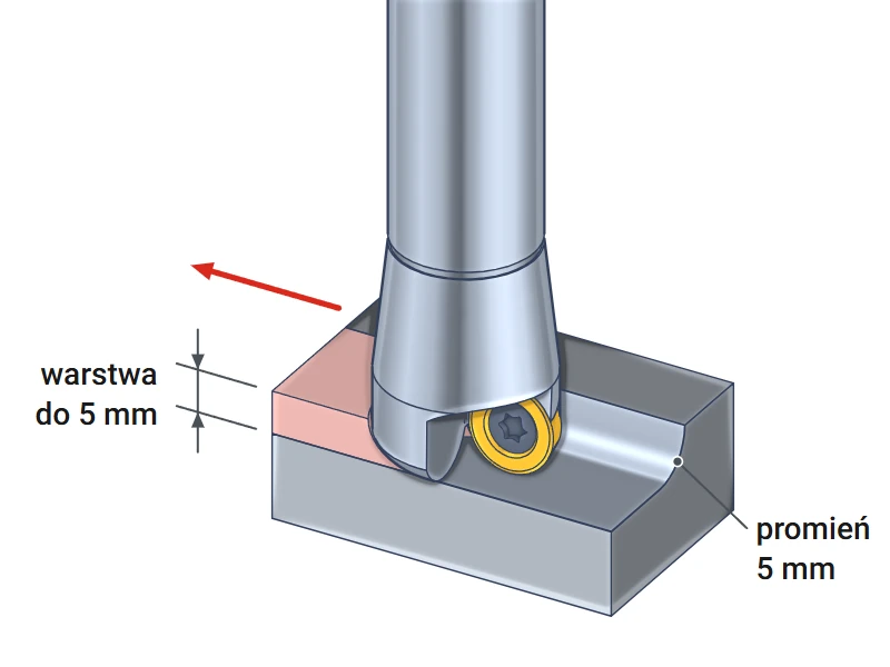
Step with a rounded corner
Use the side of the cutter to remove material along the edge of the workpiece. The bottom blends into the wall with a radius of 5 mm – the insert radius. This radius strengthens the workpiece corner. Machine a taller step in layers no deeper than 5 mm.
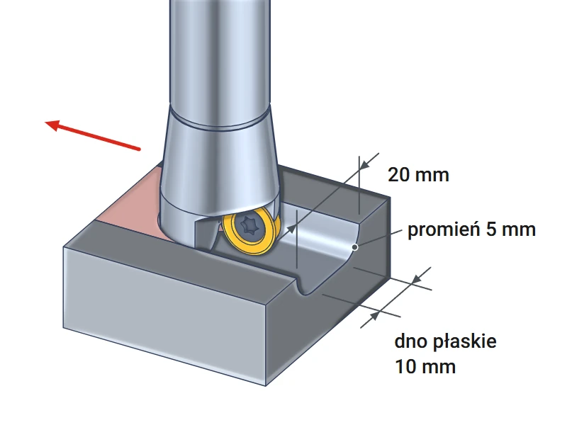
20 mm wide slot
The cutter travels through the middle of the material and cuts a slot 20 mm wide. The bottom is flat over 10 mm, with 5 mm radii at the walls. The slot reaches its full width of 20 mm at a depth of 5 mm. A shallower slot is narrower; for example, at 2 mm it is 18 mm wide.
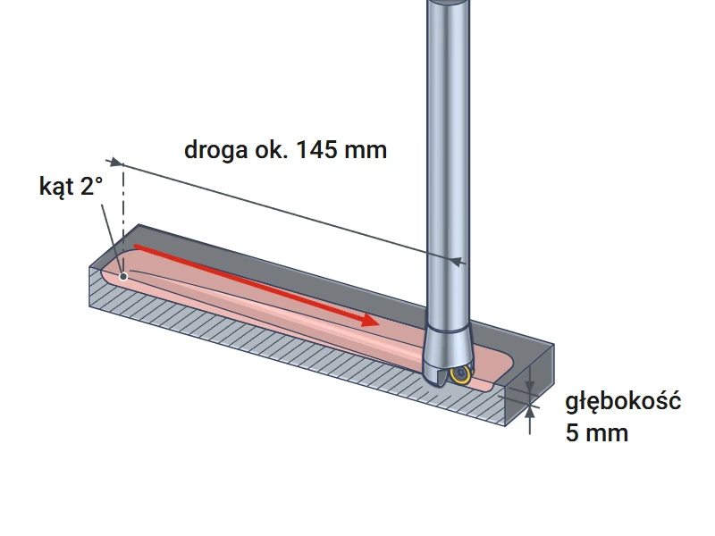
Pocket with ramp entry
The cutter descends into the material along a straight inclined path while moving sideways. No starter hole is needed. At an angle of 2°, descending to 5 mm requires approximately 145 mm of travel: 5 mm ÷ 0.035 (tangent of 2°). The cutter then clears the pocket layer by layer.
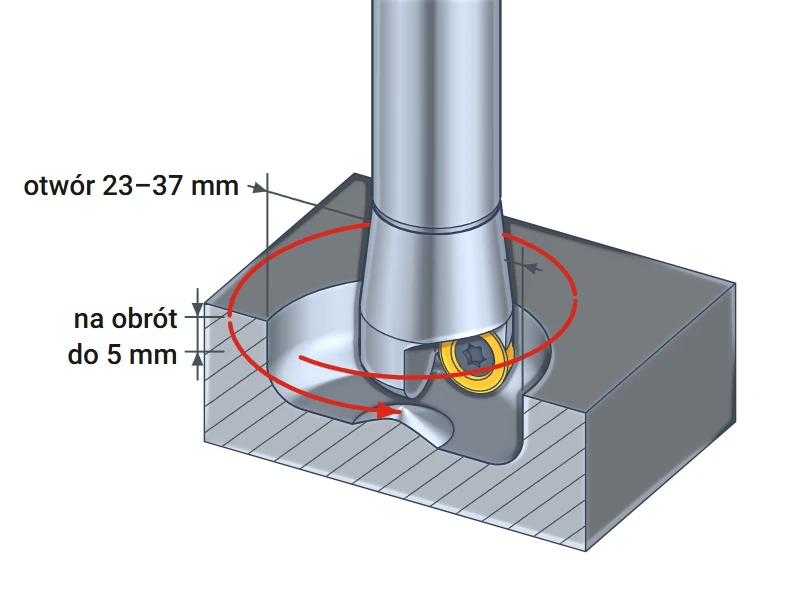
Hole milled by helical interpolation
The cutter follows a circular path and descends with each revolution. This mills a hole from 23 to 37 mm without a drill. At 30 mm, the entire bottom is smooth. At other diameters, a low cone up to 1.43 mm high remains at the center. Descend no more than 5 mm per revolution.
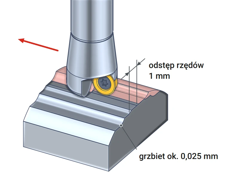
3D shape – copy milling
The cutter follows parallel passes over the curved surface of a mold or die. Low scallops remain between passes. With a stepover of 1 mm, they are approximately 0.025 mm high: 1 × 1 ÷ (8 × insert radius 5 mm). Halving the stepover reduces scallop height to one quarter.
▲
Downward entry only by ramping or helical interpolation
At the cutter axis, the insert edge is 5 mm above the end face. Plunging straight down into solid material leaves a cone of material beneath the axis. At a depth of 5 mm, it contacts the body and overloads the inserts. Enter solid material by ramping or helical interpolation.
Starting cutting data and spindle speed calculation
Cutting speed, feed per tooth and depth by material group
The table provides conservative starting values for RDMW 1003 H6310 inserts. The feed per tooth applies to a depth of 1 mm and already includes a factor of 1.7 to compensate for chip thinning. Start with these values and increase them while monitoring the chips and spindle operation. Reduce the feed when slotting and during helical interpolation.
| Workpiece material | Cutting speed vc [m/min] | Feed per tooth at a depth of 1 mm [mm] | Depth [mm] |
|---|---|---|---|
| P Structural and alloy steel | 130–200 | 0.17 | 0.5–5.0 |
| M Stainless steel | 70–130 | 0.10 | 0.5–2.5 |
| K Cast iron | 150–280 | 0.17 | 0.5–5.0 |
Spindle speed and feed calculation – steel, 150 m/min, depth 1 mm
At a depth of 1 mm, the cutter does not cut at its full diameter of 20 mm. Cutting diameter = 20 − 10 + √(10 × 10 − 8 × 8) = 16 mm. In the formula, 10 mm is the insert diameter, and 8 mm is the insert diameter minus twice the depth. Spindle speed = 1000 × cutting speed 150 m/min ÷ (3.14 × 16 mm) ≈ 2990 rpm. Feed rate = feed per tooth 0.17 mm × 2 inserts × 2990 rpm ≈ 1020 mm/min. Enter these two values in the machine program.
Calculating spindle speed using the full diameter of 20 mm gives approximately 2390 rpm. The cutting edge then runs approximately 20 percent slower than intended. For shallow cuts, always calculate using the cutting diameter.
RDMW 1003 inserts – selection and replacement
Insert designation, grade and screw tightening torque
The cutter accepts RD.. 1003 round inserts according to ISO 1832. R indicates a round insert, and D indicates a 15° clearance angle. The number 10 denotes an insert diameter of 10 mm, and 03 denotes a thickness of approximately 3.18 mm. The letter W in RDMW indicates a hole with a chamfer for a countersunk screw head.
| Insert | Workpiece material |
|---|---|
| RDMW 1003 MO H6310 Horn | steel, stainless steel; occasionally cast iron |
Horn is a Korean insert brand offered in our store. Smoxh allows any ISO-compliant RD.. 1003 insert to be used in this cutter.
Insert indexing and replacement
A round insert cuts around its entire circumference rather than along a single edge. When a section of the edge wears out, loosen the M3.5x8 screw with a Torx T15 key. Rotate the insert by several tens of degrees until a fresh section engages. Before installation, clean chips out of the seat – a chip under the insert causes runout. Tighten the screw to the 2.7 N·m torque specified by Smoxh.
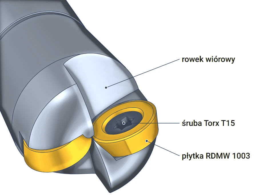
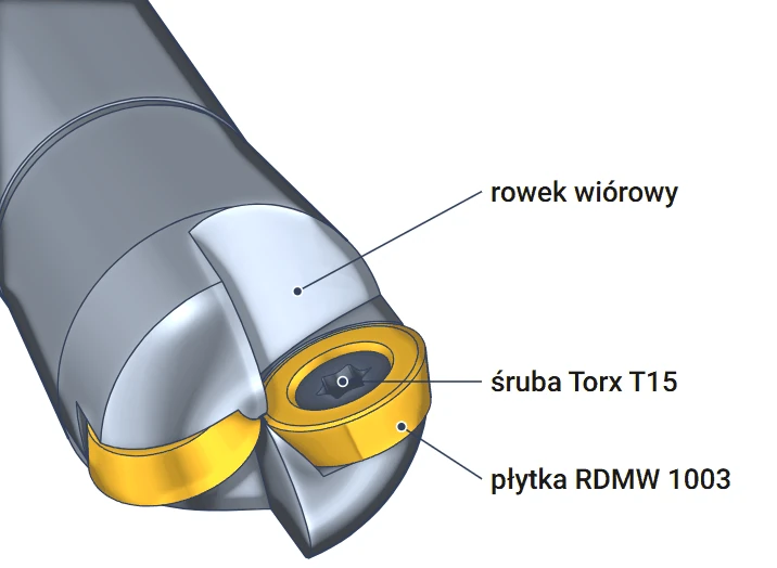
The drawing shows the milling head viewed obliquely from the end face. The insert sits in a seat in the body, with a Torx T15 screw passing through its center. A flute runs in front of the insert, carrying chips away from the cutting edge. The second insert sits on the opposite side, rotated by 180°.
▲
Cutter without internal coolant
The body has no coolant channel. Clear chips from pockets and holes with a stream of coolant or compressed air from the machine nozzle. A chip left in a pocket is cut again by the cutter, damaging the insert edge.
Ø20 mm indexable end mill for Ø10 mm round inserts Smoxh RD1003 combines a cutter for flat surfaces, slots and holes with a copy milling cutter. It uses two RDMW 1003 inserts and cuts to a depth of up to 5 mm. It is most productive with shallow cuts at a high feed rate. It mills holes from 23 to 37 mm by helical interpolation.
Questions about the RD1003 D20 round-insert cutter
Inserts, holes, depth, cutter selection
ISO RD.. 1003 round inserts with a diameter of 10 mm, e.g., RDMW 1003 MO H6310 from the Korean brand Horn. The insert is secured with an M3.5x8 screw with a Torx T15 recess, tightened to 2.7 N·m.
A hole from 23 to 37 mm. At 30 mm, the entire bottom is smooth. At 23 mm and 37 mm, a cone approximately 1.43 mm high remains at the center of the bottom; at 25 mm and 35 mm, it is approximately 0.67 mm high.
Up to 5 mm per pass, which is half the insert diameter. Machine deeper shapes in layers. A depth of approximately 1 mm with a higher feed rate provides the highest productivity.
Choose a round-insert cutter for 3D shapes, radiused transitions and rapid stock removal with shallow passes. Choose a 90° cutter with APKT inserts for square shoulders and sharp corners at the bottom.
Product accessories


Reviews
No customer reviews for the moment.
Shipping
All orders are delivered by courier company GLS. For orders exceeding 369 PLN gross shipping is FREE
| Courier GLS | Przelew24 / Prepayment | 14,76 zł gross | Delivery time 1 working day |
| Courier GLS | Cash on delivery | 17,26 zł gross | Lead time 1 working day |
Recommended for you


This website uses its own and third-party cookies to improve our services and show you advertising related to your preferences by analyzing your browsing habits. To give your consent to its use, press the Accept button.
Cookie preferences
Functional cookiesTechnical
Functional cookies are strictly necessary to provide the services of the shop, as well as for its proper functioning, so it is not possible to refuse their use. They allow the user to browse through our website and use the different options or services that exist on it.
Advertising Cookies
These are cookies that collect information about the advertisements shown to users of the website. They can be anonymous, if they only collect information about the advertising spaces shown without identifying the user, or personalised, if they collect personal information about the user of the shop by a third party, for the personalisation of these advertising spaces.
Analytics cookies
Collect information about the user's browsing experience in the shop, usually anonymously, although sometimes they also allow the user to be uniquely and unequivocally identified in order to obtain reports on the user's interests in the products or services offered by the shop.