




- 98% satisfied customers
- 72h delivery
- 30 dni na zwrot

Description
Indexable end mill Ø20 mm – 90° end mill for APKT 1135 inserts
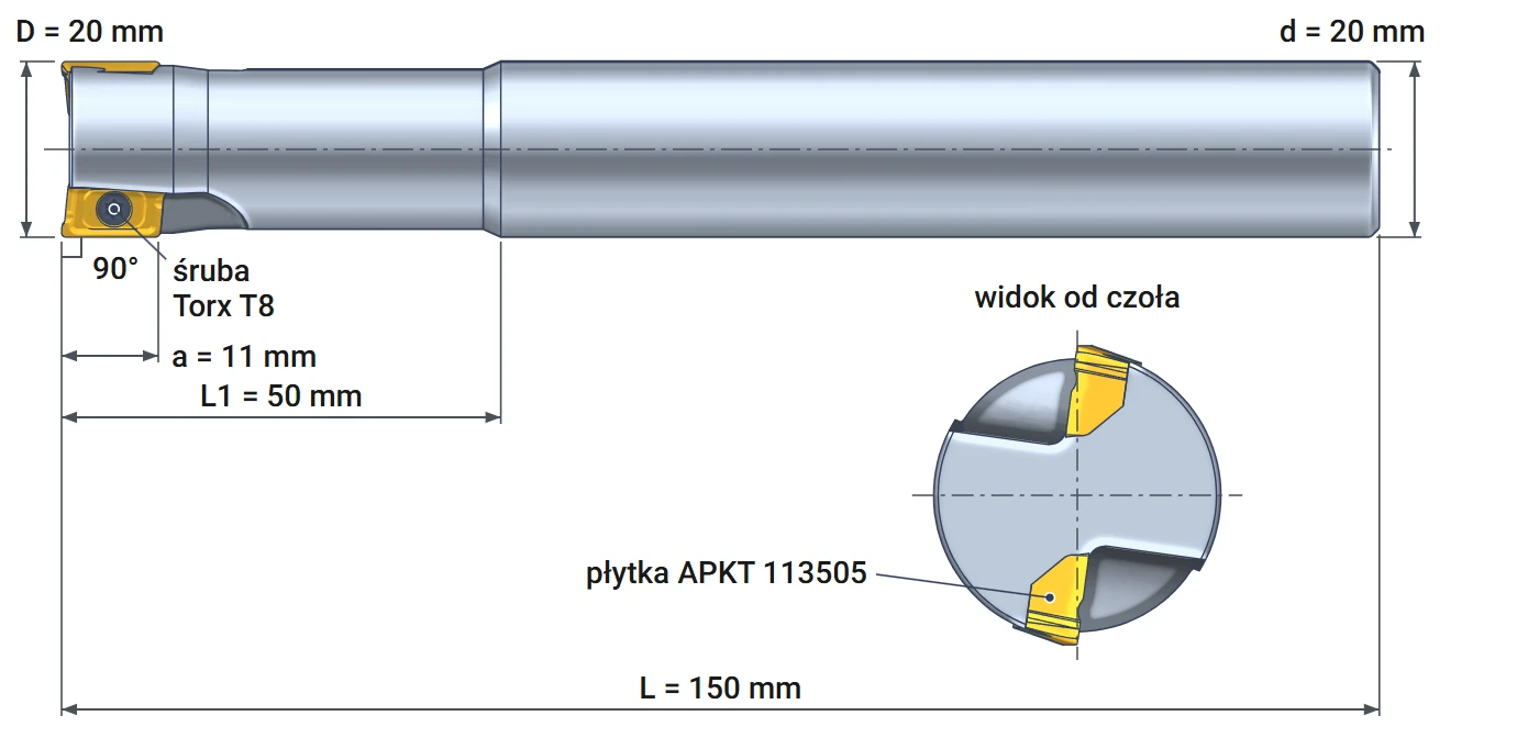
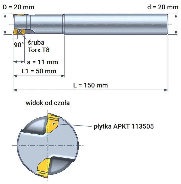
Technical data and dimensions – Varel BAP 300R, 20 mm straight shank
| Technical data | |
|---|---|
| Cutter diameter D | 20 mm |
| Shank diameter d | 20 mm, plain straight shank |
| Max. depth of cut a | 11 mm |
| Length to shank L1 | 50 mm |
| Overall length L | 150 mm |
| Entering angle | 90 degrees |
| Number of inserts Z | 2 |
| Inserts | APKT 1135 and APMT 1135, e.g., APKT 113505 |
| Coolant supply | external |
| Insert screw | M2.5x6, Torx T8 |
| Manufacturer | Varel (BAP 300R C20-20-150) |
Diameter20 mm
Depth of cutup to 11 mm
Inserts2 × APKT 1135
Coolant supplyexternally
Indexable end mill Ø20 mm The Varel BAP 300R cuts at 90° with two APKT 1135 inserts. It can machine a square shoulder, slot, pocket, and flat surface in steel, cast iron, and aluminum. It can also enter solid material along a helical path and produce a hole from 28 to 39 mm without a drill. When an edge becomes dull, index the insert and continue milling.
The 20 mm straight shank is smooth, without a flat. The catalog specifies a tolerance from −0.005 to −0.015 mm, making it suitable for a precision collet chuck or hydraulic chuck. With a length of 150 mm, extend the end mill from the holder only as far as the workpiece requires – every millimeter of overhang increases deflection. The body has no coolant channel. Supply coolant or compressed air through the machine nozzles, directing the stream onto the inserts.
Six operations with a 90° end mill – from a flat surface to a hole
Face milling, shoulder milling, slotting, ramping, helical interpolation, plunge milling
The 90° end mill for APKT 1135 and APMT 1135 inserts performs face milling, 90° shoulder milling, slotting, plunge milling, helical interpolation, and contour milling. Each operation uses a different insert edge. The 11 mm long side edge forms the wall. The bottom edge smooths the floor and allows downward cutting. The drawings show cutter movement and the material removed.
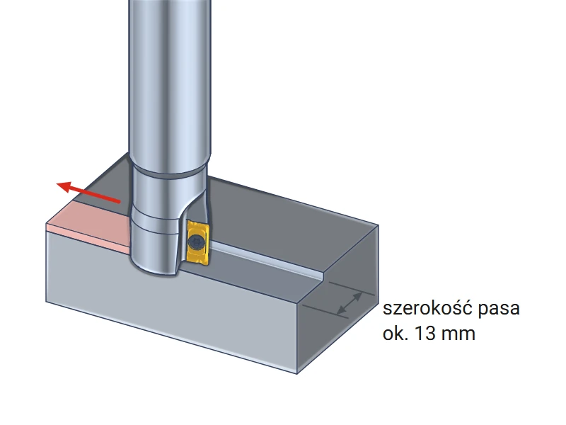
Face milling
Feed the end mill across the workpiece at a shallow depth of cut. The bottom insert edge, with a short chamfer near the corner, smooths the surface. A single pass removes a strip up to approximately 13 mm wide, or about two-thirds of the diameter. This is sufficient for ledges, end faces, and casting risers.
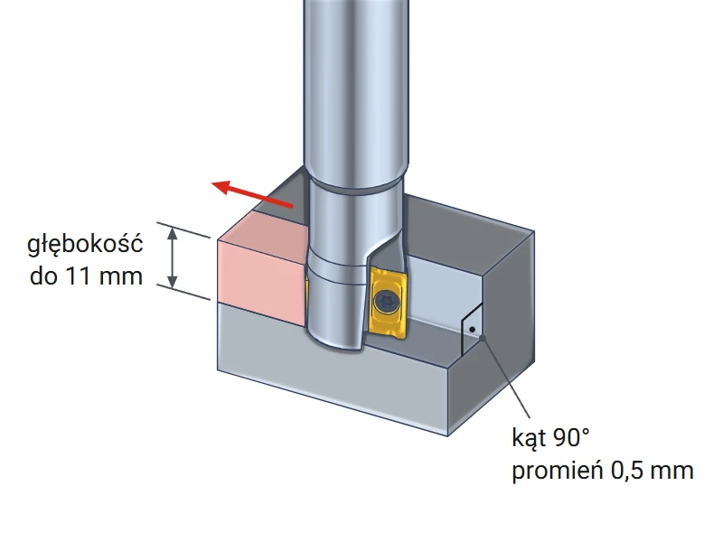
90° shoulder and contour
The side edge of the insert is parallel to the cutter axis, producing a wall perpendicular to the floor. A single pass can machine up to 11 mm of wall height. A 0.5 mm radius remains at the corner between the wall and floor, matching the insert corner radius.
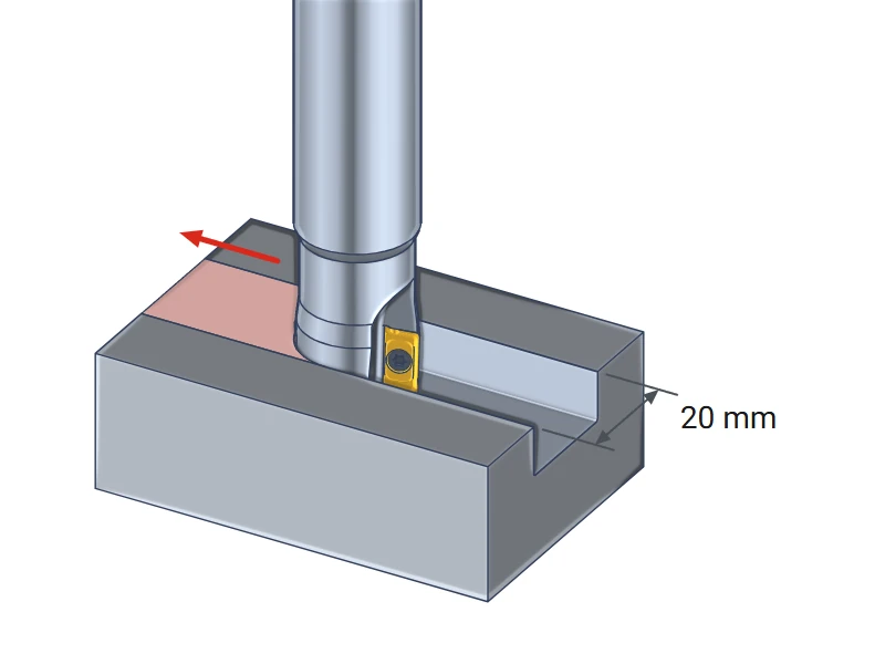
20 mm wide slot
The end mill travels through the material and cuts a 20 mm wide slot in a single pass. The full leading side of the cutter is engaged, and both inserts cut alternately. Use a smaller depth of cut than for shoulder milling and ensure effective chip evacuation.
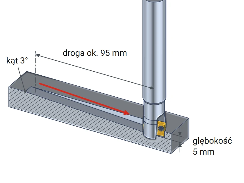
Ramping – angled entry
The end mill descends into the material along an inclined straight line while moving sideways. The bottom insert edge cuts downward, eliminating the need for a starter hole. This provides entry into a pocket or closed slot. At an angle of 3°, descending to a depth of 5 mm requires approximately 95 mm of travel.
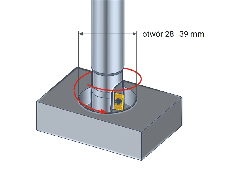
Helical interpolation – a hole without a drill
The end mill follows a circular path, descending with each revolution. This produces a flat-bottom hole from 28 to 39 mm. Set the hole diameter in the machine program rather than by selecting a drill. This also provides smooth entry into a closed pocket.
Plunge milling
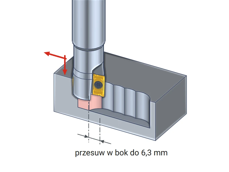
The end mill plunges axially downward, retracts, and steps sideways, much like a drill. Each plunge removes material only near the cutter periphery. Keep the stepover to approximately 6.3 mm: this is how far the insert extends inward from the periphery. The cutting force then acts mainly along the axis.
A hole without a drill – helical milling
Minimum and maximum hole diameters for a 20 mm end mill with a 0.5 mm insert corner radius
Helical milling is also known as helical interpolation. The end mill rotates about its own axis while the machine simultaneously moves it in a circle and downward. The path is shaped like a spring. A single 20 mm end mill can thus produce holes of various diameters.
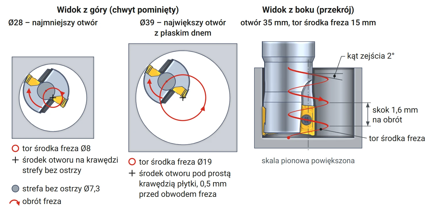
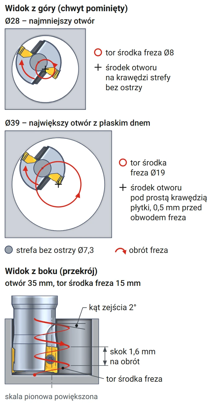
The drawing shows the end mill in the smallest and largest holes, viewed from above. The gray disc at the cutter center is the area without cutting edges. The side view shows the cutter center path and pitch, which is the downward travel per revolution.
Minimum hole diameter: 28 mm
The bottom insert edge extends approximately 6.35 mm inward from the cutter periphery. It therefore ends approximately 3.65 mm from the cutter axis (10 − 6.35 mm). A disc approximately 7.3 mm in diameter without cutting edges remains at the cutter center. To remove all material there, the cutter center must follow a circle with a radius of at least 3.65 mm. Minimum hole diameter = 20 + 2 × 3.65 ≈ 28 mm. In a smaller hole, a core remains beneath the cutter and strikes the body.
Maximum flat-bottom hole diameter: 39 mm
The floor is flat when the hole center lies beneath the straight section of the bottom insert edge. This section ends at the corner, 0.5 mm short of the cutter periphery. Maximum hole diameter = 2 × 20 − 2 × 0.5 = 39 mm. Produce a larger hole in two steps: first use helical interpolation up to 39 mm, then enlarge it with circular passes.
Calculation: helical pitch for a 35 mm hole
Calculate the pitch along the cutter center path, not from the hole diameter. Path diameter = hole diameter 35 mm − cutter diameter 20 mm = 15 mm. One revolution covers a distance of 3.14 × 15 ≈ 47.1 mm. At a ramp angle of 2°, the pitch is 47.1 × 0.035 (tangent of 2°) ≈ 1.6 mm. A through hole in a 20 mm plate therefore requires approximately 12 revolutions. The pitch must not exceed 11 mm, which is the maximum insert depth of cut.
The shank has the same diameter as the cutter, 20 mm. In a hole deeper than 50 mm, the shank would contact the wall. This is the length to the shank, over which the body is smaller than the cutting diameter.
▲
Axial entry only into a predrilled hole
The approximately 7.3 mm area at the cutter center has no cutting edges. Plunging straight down into solid material causes the core to bear against the body and overload the inserts. Enter solid material by ramping or helical interpolation. Axial entry is possible only into a previously drilled hole on the same axis, with a diameter of at least 8 mm.
APKT 113505 inserts – material selection and replacement
The insert grade determines material suitability; the end mill remains the same
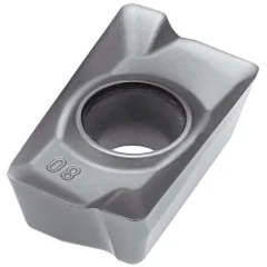
The BAP 300R C20-20-150 end mill accepts APKT 1135 inserts. The letter A denotes a 85° parallelogram, in practice a rectangular insert. P denotes a 11° clearance angle: the insert has positive geometry and cuts freely. The numbers 1135 differ from the ISO designation: 11 is the cutting edge length in millimeters, while 35 denotes a thickness of 3.5 mm. The final digits 05 indicate a corner radius of 0.5 mm.
The catalog specifies APMT 1135 inserts for this end mill. An APKT insert of the same size has the same shape and differs only in tolerance class: K is more precise than M. Both fit the same insert pocket.
| Insert | Workpiece material | Notes |
|---|---|---|
| APKT 113505 PDER H6310 Horn | steel, stainless steel | PVD coating |
Horn is a Korean insert brand available in our store. Select the insert grade for the workpiece material; the end mill remains the same.
Replacing and indexing the insert
The insert has two cutting edges. When one becomes dull, loosen the M2.5x6 screw with a Torx T8 key and rotate the insert by 180°. Remove chips from the pocket before installation: a chip beneath the insert lifts it and causes runout. The catalog does not specify a tightening torque; use the value from the insert manufacturer's data sheet. Replace all inserts together so they cut at the same height.
Cutting data – starting values for APKT inserts
Speed, feed per tooth, and depth by material group
The table provides conservative starting values for milling a 90° shoulder with APKT inserts. Start at the lower limit and increase while monitoring the chips and spindle operation. Reduce the feed rate for slotting, ramping, and helical interpolation.
| Workpiece material | Cutting speed vc [m/min] | Feed per tooth fz [mm] | Depth ap [mm] | Width ae [mm] |
|---|---|---|---|---|
| P Structural and alloy steel | 130–200 | 0.10–0.20 | 1.0–4.0 | 6–14 |
| M Stainless steel | 70–130 | 0.06–0.15 | 0.5–2.0 | 5–12 |
| K Cast iron | 150–280 | 0.10–0.25 | 1.0–5.0 | 8–14 |
| N Aluminum (K10 insert) | 300–600 | 0.10–0.25 | 1.0–6.0 | 8–14 |
Spindle speed and feed rate calculation – steel, 150 m/min
Spindle speed = 1000 × cutting speed 150 m/min ÷ (3.14 × cutter diameter 20 mm) ≈ 2390 rpm. Feed rate = feed per tooth 0.10 mm × 2 inserts × 2390 rpm ≈ 480 mm/min. Enter these two values in the machine program. In aluminum, at 400 m/min, spindle speed increases to approx. 6370 rpm – check that the spindle can reach this speed.
Indexable end mill Ø20 mm The Varel BAP 300R replaces a cutter for 90° shoulders, slots and faces, as well as a cutter for holes. Helical interpolation produces flat-bottom holes from 28 to 39 mm. It uses two APKT 113505 inserts and has a 20 mm straight shank and external coolant. The maximum depth of cut is 11 mm.
Questions about the BAP 300R C20-20-150 indexable end mill
Inserts, tool holder, coolant
ISO APKT 1135 and APMT 1135 inserts, e.g., APKT 113505 with a 0.5 mm corner radius. Grade H6310 from the Korean brand Horn is suitable for steel and stainless steel. The insert is secured with an M2.5x6 screw with a Torx T8 recess.
A collet chuck with a 20 mm collet or a hydraulic chuck for a 20 mm shank. Both clamp the smooth shank around its entire circumference. Extend the end mill from the holder only as far as the machining depth requires.
Externally: use the machine nozzles to direct coolant or compressed air onto the inserts. The stream should clear chips from the pocket and hole. The BAP series catalog does not list a version with a coolant channel.
Product accessories


Carbide insert APKT 100305 PDFR K10 Horn
Reference: 0000004237 In stock > 10 items
€3.16
€3.88 brutto

Carbide insert APKT 113505 PDER H2 H6310 Horn
Reference: 11535 In stock > 10 items
€3.16
€3.88 brutto
Reviews
No customer reviews for the moment.
Shipping
All orders are delivered by courier company GLS. For orders exceeding 369 PLN gross shipping is FREE
| Courier GLS | Przelew24 / Prepayment | 14,76 zł gross | Delivery time 1 working day |
| Courier GLS | Cash on delivery | 17,26 zł gross | Lead time 1 working day |
Recommended for you


This website uses its own and third-party cookies to improve our services and show you advertising related to your preferences by analyzing your browsing habits. To give your consent to its use, press the Accept button.
Cookie preferences
Functional cookiesTechnical
Functional cookies are strictly necessary to provide the services of the shop, as well as for its proper functioning, so it is not possible to refuse their use. They allow the user to browse through our website and use the different options or services that exist on it.
Advertising Cookies
These are cookies that collect information about the advertisements shown to users of the website. They can be anonymous, if they only collect information about the advertising spaces shown without identifying the user, or personalised, if they collect personal information about the user of the shop by a third party, for the personalisation of these advertising spaces.
Analytics cookies
Collect information about the user's browsing experience in the shop, usually anonymously, although sometimes they also allow the user to be uniquely and unequivocally identified in order to obtain reports on the user's interests in the products or services offered by the shop.