



Description
HTA Horn · narrow grooves on shafts and in bores
| Technical data | |
|---|---|
| Designation | 16 IR/EL 1.20 HTA |
| Cutting width W | 1.20 mm |
| Groove depth T max | 1.4 mm |
| Insert size | 16 · IC 9.525 mm |
| Cutting edges | 3 corners |
| Material / grade | cemented carbide / HTA |
| External tool holders | left-hand SEL / PEL, size 16 |
| Internal tool holders | right-hand SIR / PIR, size 16 |
| Brand / product code | Horn / 0000003442 |
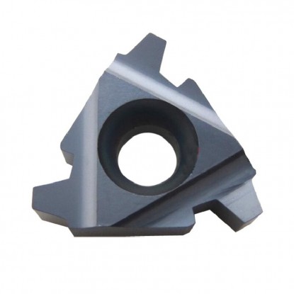
16 IR/EL 1.20 HTA · product photo


Retaining ring grooving insert 16 IR/EL 1.20 HTA Horn is used to cut narrow circumferential grooves on shafts and inside bores. The 1.20 mm cutting width allows a groove to be produced with a single radial infeed. Three corners allow successive edges to be used by indexing the insert. One edge cuts in a given position; the others remain available for use after it wears out.
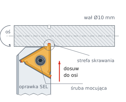
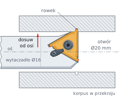
The same insert, the appropriate holder, and radial infeed
On the shaft surface · left-hand SEL / PEL holder
In the bore wall · right-hand SIR / PIR boring bar
Illustrative diagrams. Gold highlights the insert, and red arrows indicate infeed. Ø10 and Ø20 mm are example workpiece diameters.
In external grooving, the cutting edge moves toward the shaft axis. Inside a bore, infeed moves it away from the axis toward the wall. In both cases, the groove is formed around the entire circumference of the rotating workpiece. The boring bar determines the minimum bore diameter, so select it before planning the operation.

Seat for a ring that limits axial movement of a component.

Seat for a ring that locates a component inside a housing.
Retaining ring grooves require the width, depth, and tolerances specified in the documentation for the particular ring. Ring thickness alone does not determine groove width. The insert can also be used for narrow locating grooves, provided their dimensions are within the cutting edge's capacity.
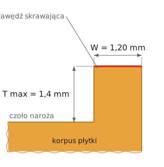
Cutting width and groove depth refer to different dimensions
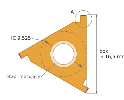
Top view · rotate the insert by 120° when the edge becomes dull
W = 1.20 mm · T max = 1.4 mm
Dimension W specifies the tooth width, while T max specifies its maximum reach into the material. Check the actual groove width after machining; tool setup and vibration also affect it. Size 16 refers to the insert format, and IC denotes the inscribed circle diameter. When selecting the tool, compare both cutting tip dimensions with the part drawing. A narrow groove may require less than the maximum reach, especially on small parts. Determine the final depth from the groove bottom dimension.
Calculate the groove bottom diameter on a shaft using the formula d2 = d − 2·T. For a Ø20 mm shaft and a full depth of 1.4 mm: d2 = 20 − 2 · 1.4 = 17.2 mm. Measure this diameter after machining, before installing the retaining ring. In a bore, the bottom diameter increases: D2 = D + 2·T.
Insert pocket size, cutting hand, cutting edge width, and grade
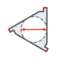
Size 16 insert pocket; IC 9.525 mm.
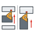
Right-hand internal or left-hand external.
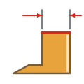
Nominal 1.20 mm groove in a single plunge.

Grade designation from the Korean brand Horn.
The IR/EL designation indicates two operating configurations for the same insert in size 16 threading holders. For internal grooves, select a right-hand SIR or PIR threading boring bar. For external machining, use a left-hand SEL or PEL turning tool. Also check the shim, clamping system, and clearance between the tool and workpiece.
SER and SIL holders require the mirror-image ER/IL insert.
Short overhang, secure clamping, and efficient chip evacuation
Set the cutting edge at center height within ±0.1 mm and minimize holder overhang. Direct coolant into the cutting zone to help remove chips from the narrow slot. Select the cutting speed and feed to suit the material, HTA grade, and setup rigidity. Verify the settings with a trial cut and inspection of the first groove.

Do not exceed the cutting tip reach. Excessive infeed may bring the insert body into contact with the workpiece. Face grooving, parting off to center, and longitudinal turning require separate tool selection.
The manufacturer does not specify cutting speeds or feeds for HTA grade. Determine the settings through trial cuts; do not apply cutting data from other grades or wider inserts.
The 16 IR/EL 1.20 HTA retaining ring grooving insert machines external grooves on shafts and internal grooves in bores. Size 16 is shared across the entire IR/EL series, with widths from 0.40 to 3.0 mm. A wider groove can therefore be machined with an insert from the same family without changing the holder. Check the depth for each width on its product page, as T max varies within the series.
Key information before selecting a tool
Yes. The IR/EL insert works in right-hand SIR and PIR boring bars and left-hand SEL and PEL external holders in size 16. Check the compatibility of the insert pocket, shim, and clamping system on the specific holder.
No. It is the nominal cutting edge width W. The maximum groove depth T max is 1.4 mm; a shallower depth is set by radial infeed.
Select the insert to match the groove width and depth specified in the retaining ring documentation. Account for the tolerance and required corner radii; ring thickness alone is not sufficient.
A wider groove requires a suitable insert or a verified multiple-plunge strategy. Do not assume that a narrow tooth can safely perform side turning. Check the machining strategy permitted for the tool.
No customer reviews for the moment.
All orders are delivered by courier company GLS. For orders exceeding 369 PLN gross shipping is FREE
| Courier GLS | Przelew24 / Prepayment | 14,76 zł gross | Delivery time 1 working day |
| Courier GLS | Cash on delivery | 17,26 zł gross | Lead time 1 working day |
This website uses its own and third-party cookies to improve our services and show you advertising related to your preferences by analyzing your browsing habits. To give your consent to its use, press the Accept button.