






Description
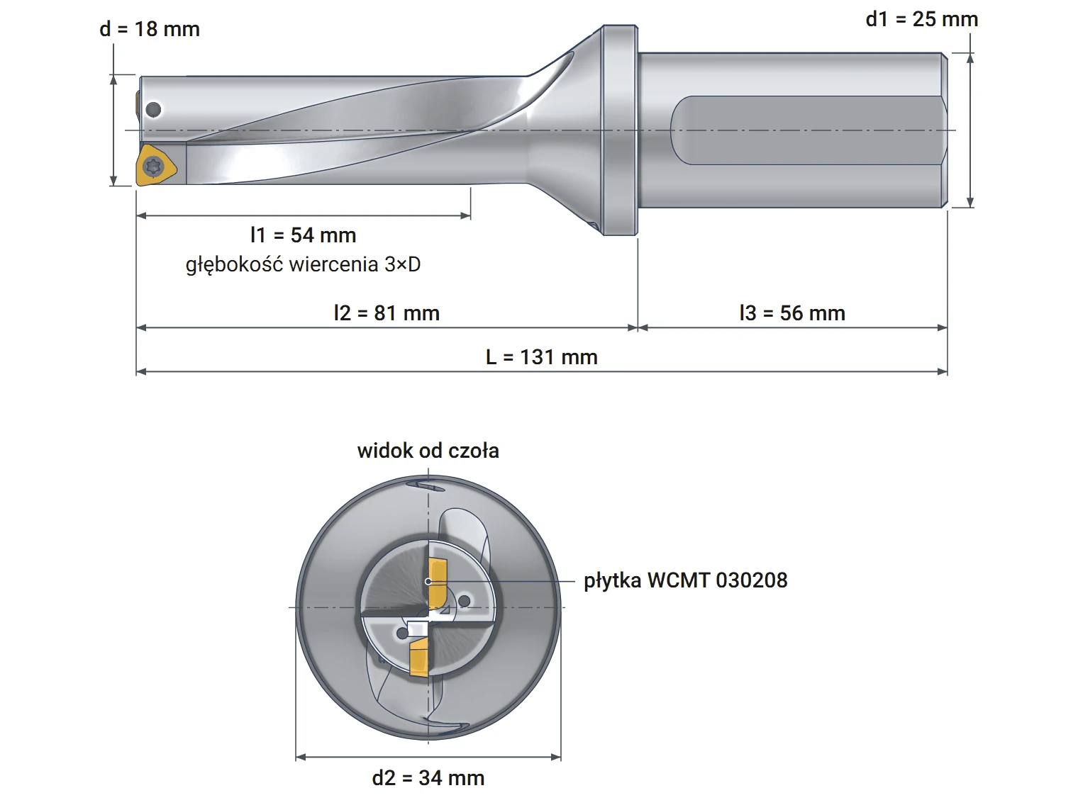
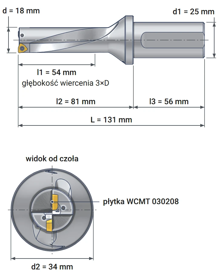
Varel SD18-54-C25: drilling depth 54 mm, shank 25 mm, WCMT 030208 inserts
| Technical data | |
|---|---|
| Drilling diameter | 18 mm |
| Drilling depth l1 | 54 mm (3×D) |
| Length to flange l2 | 81 mm |
| Shank length l3 | 56 mm |
| Overall length L | 131 mm |
| Shank diameter d1 | 25 mm, Weldon flat |
| Flange diameter d2 | 34 mm |
| Inserts | 2 × WCMT 030208 |
| Insert screw | M2.5x6.5, Torx T8 |
| Coolant supply | internal, 2 channels |
| Hole tolerance | 0/+0.25 mm |
| Varel designation | SD18-54-C25 |
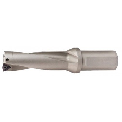
Ø18 indexable drill Varel drills holes with a diameter of 18 mm and a depth of up to 54 mm, or three diameters. According to the drill size table in PN-86/M-59601, this is the tap drill size for an M20x2 fine thread. Instead of a steel cutting edge, it has two replaceable WCMT 030208 cemented carbide inserts. A dull edge is replaced by indexing the insert, while the body remains in service. The drill operates on machining centers and CNC lathes.
Coolant flows through two channels inside the drill directly beneath the inserts. It flushes chips out of the hole and cools the cutting edges. The 25 mm shank has a Weldon flat for the holder screw, preventing the drill from rotating in the holder. This type of indexable drill is also called an insert drill or U-drill.
How deep the drill can drill and what remains at the bottom
The flutes end 54 mm from the drill face. Up to this depth, chips have a path out of the hole. The Varel catalog therefore specifies a drilling depth of 3×D, or 3 × 18 mm = 54 mm. For holes up to 90 mm deep, use the Ø18 5D indexable drill.
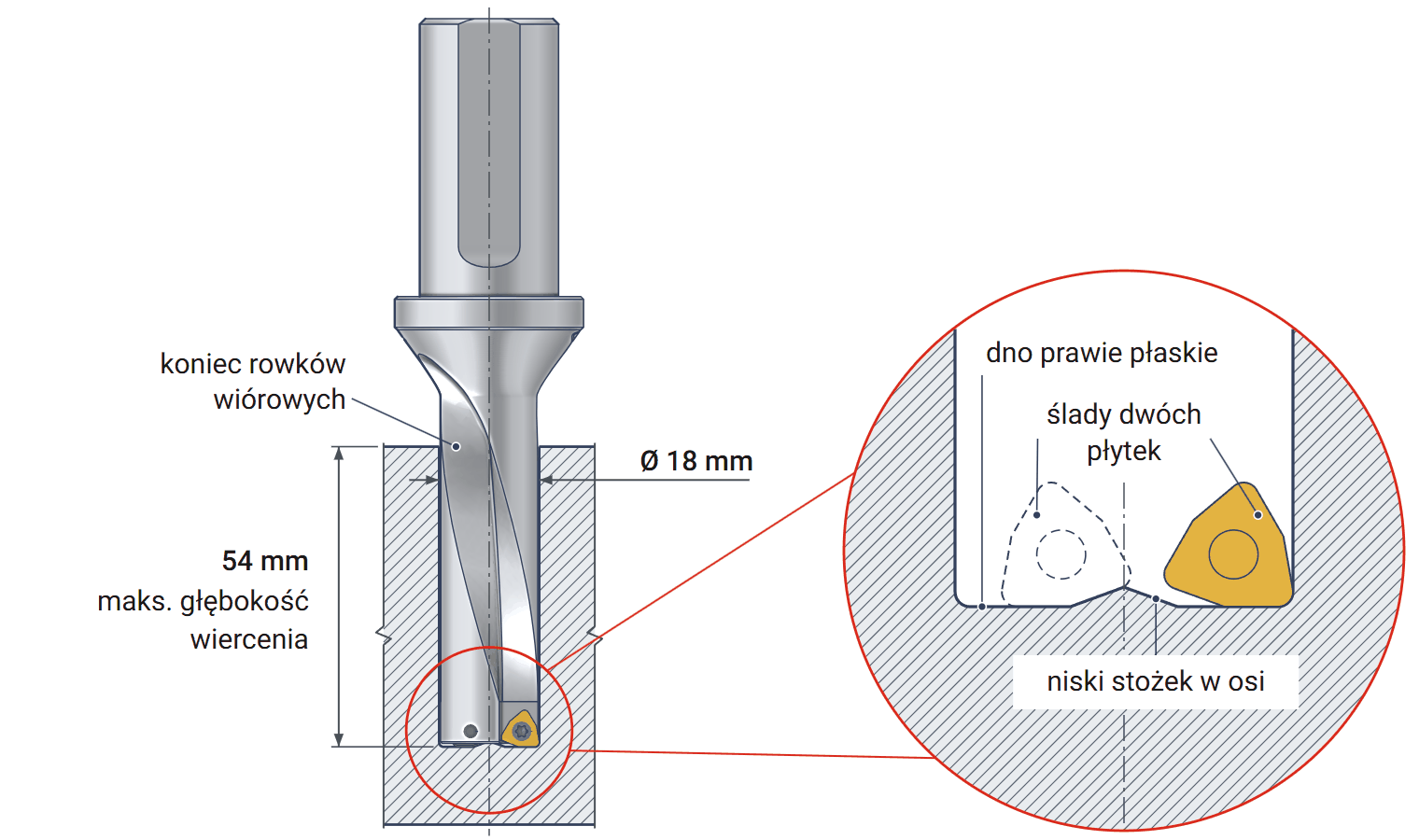
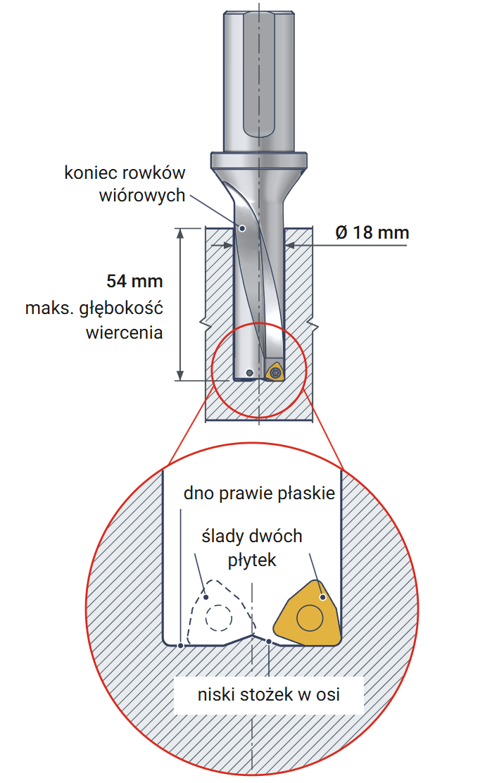
The hole bottom does not have the cone left by a 118° twist drill. It is nearly flat, with slight undulations left by the two inserts. Only a low cone remains at the center.
The resulting hole diameter ranges from 18.00 to 18.25 mm. This is the range allowed by the Varel catalog for 2×D and 3×D drills. Holes requiring a specified fit are reamed or bored after drilling.
Center insert, peripheral insert and self-centering
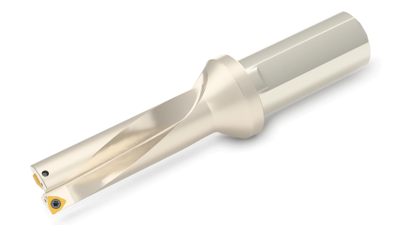
Both inserts sit on the drill face: the center insert near the axis and the peripheral insert at the edge of the body. The flutes guide chips from the inserts toward the shank.
The same WCMT 030208 insert is used in both pockets. The center insert cuts from the hole axis, while the peripheral insert cuts the 18 mm diameter. Their cutting edges overlap, so no uncut ring remains at the bottom.
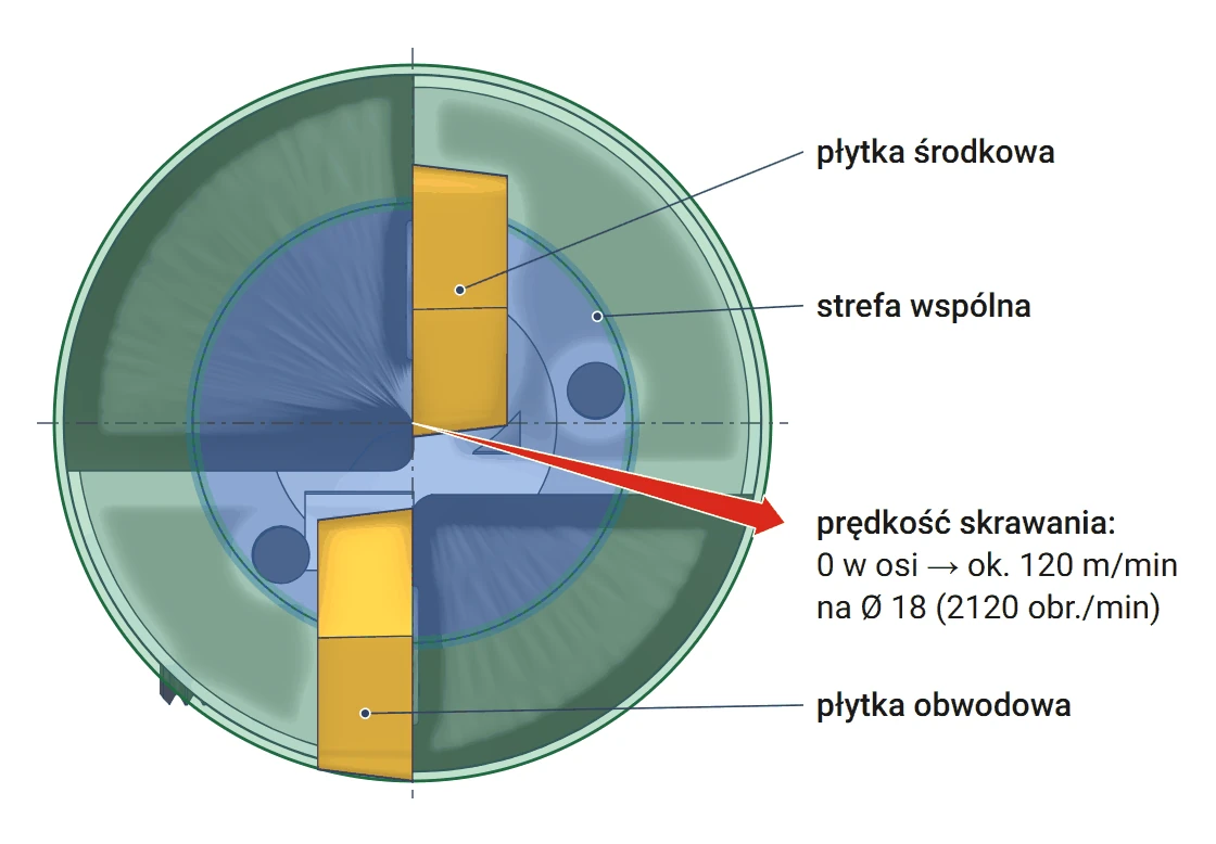
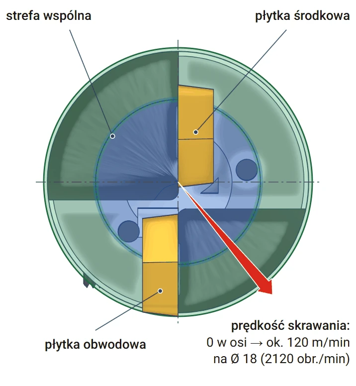
Cutting speed increases from zero at the axis to its maximum at the periphery. Near the axis, the insert pushes material aside more than it cuts it. As a result, the center insert is more prone to chipping, while the peripheral insert wears due to heat. Check both inserts whenever indexing the cutting edges.
The two inserts guide the drill along its axis, so spot drilling is not required. Drilling starts directly in solid material. A pilot hole in the workpiece must not exceed 4.5 mm, or 1/4 of the drill diameter. A larger hole pulls the drill off-axis.
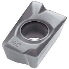
The insert designation is interpreted according to ISO 1832. W denotes a 80° trigon with three cutting edges. C indicates a 7° clearance angle, M the tolerance class, and T a screw hole and chip breaker. 03 indicates the insert size (inscribed circle 5.56 mm), 02 the thickness of 2.38 mm, and 08 the corner radius of 0.8 mm. Our store offers the Horn WCMT 030208 insert for indexable drills.
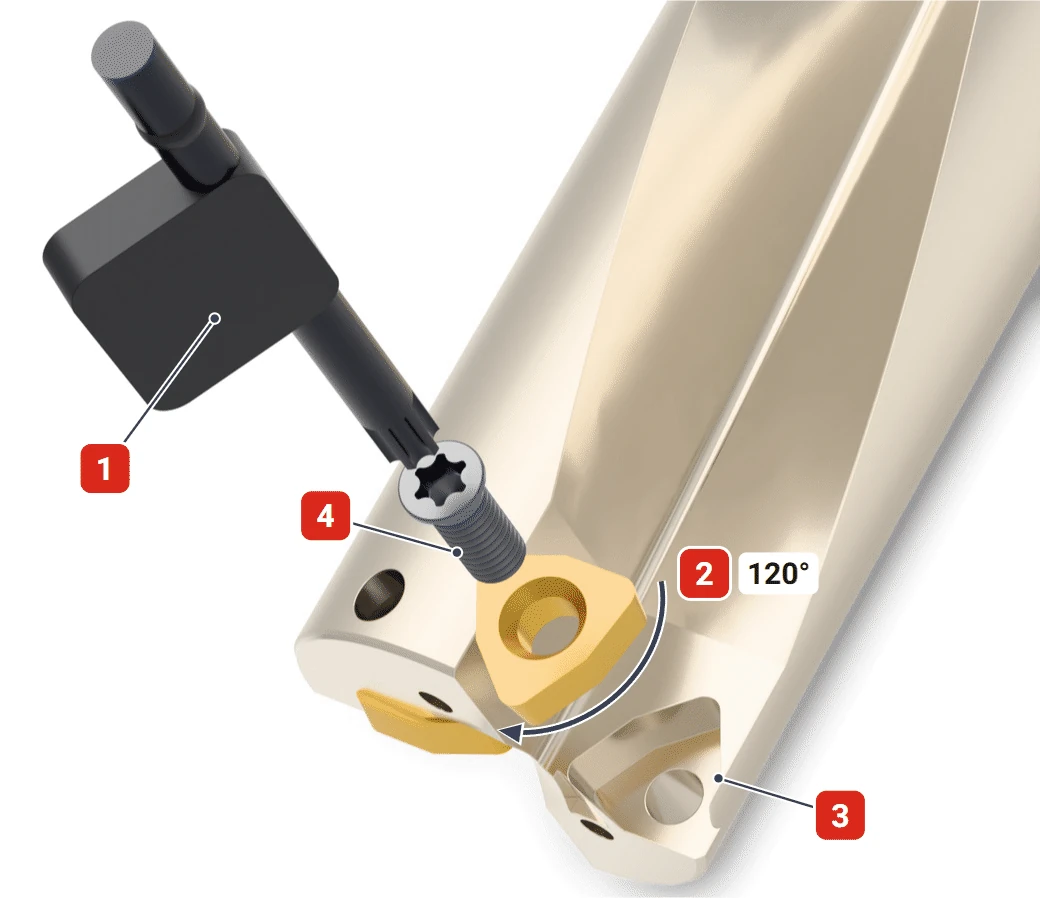
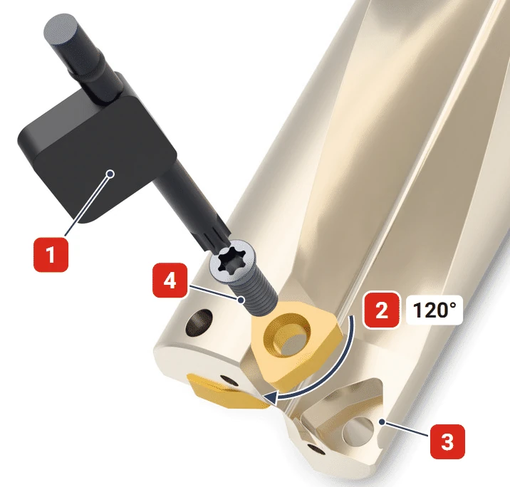
After loosening the screw, rotate the insert in its pocket by 120° to bring the next cutting edge into use. Each WCMT 030208 insert has three edges, so a set of two inserts provides three indexing positions.
Key: Torx T8
Rotation: 120°
Chips: to be removed
Screw: M2.5x6.5
Included: body, Torx T8 key and two M2.5x6.5 screws.
Coolant, axis alignment and difficult material entry
Coolant is supplied through the spindle and drill at a pressure of at least approximately 4 bar. This is the value specified in the Varel catalog for 2×D and 3×D drills. Mount the drill in a rigid holder with minimal runout relative to the spindle.
With externally supplied coolant, the drill can drill up to 1.5 × 18 mm = 27 mm in a single pass. For deeper holes, retract the drill every few millimeters to flush out chips.
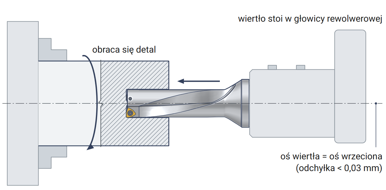
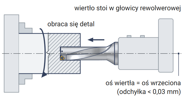
On a lathe, the drill remains stationary in the turret while the workpiece rotates. The drill axis must align with the spindle axis within 0.03 mm.
Bar: Drill Ø and length
Indicator: on the chuck, 360° rotation
Deviation: below 0.03 mm
Peripheral insert: parallel to the X axis
Peripheral insert on the outer side of the turret; check axis alignment again after a lathe collision.
When drilling through, a disc of material is ejected from the bottom of the workpiece at high speed. Keep the lathe guard closed throughout drilling.
It is best to drill into a surface perpendicular to the drill axis. On other surfaces, the inserts are loaded unevenly and the drill moves off-axis. In this case, reduce the feed to 1/3 of the recommended value.
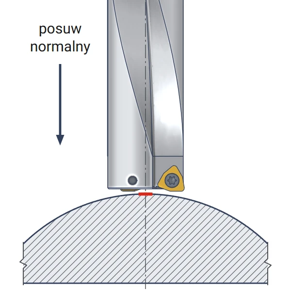
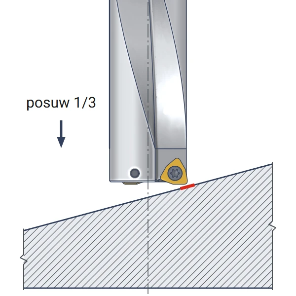
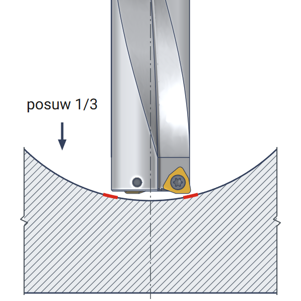
On uneven surfaces, reduce the feed at entry and breakthrough to protect the insert from chipping. Drill intersecting holes at approximately 1/3 of the recommended feed.
| Symptom | Cause | What to adjust |
|---|---|---|
| Chipped center insert edge | Cutting speed drops to zero at the axis and the insert pushes material aside | Lower feed at entry and breakthrough, tougher insert grade |
| Rapid peripheral insert wear | Cutting speed and temperature are highest at the periphery | Cutting speed at the lower end of the range, through-tool coolant |
| Drill moves off-axis | Inclined or concave surface, pilot hole larger than 4.5 mm | Feed at 1/3 of the recommended value on entry, pilot hole up to 4.5 mm |
| Chips accumulate in the flutes | External coolant at depths greater than 27 mm or pressure below 4 bar | Through-tool coolant from 4 bar; use peck drilling with external coolant |
| Hole wider than 18.25 mm | Holder runout, axis misalignment over 0.03 mm on a lathe | Rigid holder, adjust turret axis alignment using an indicator |
Cutting speed, spindle speed and feed – starting values
The table lists the lower cutting speed limit from the Varel catalog. Feed per revolution for the WCMT 030208 insert ranges from 0.05 to 0.12 mm. The starting value is 0.06 mm; then gradually increase the feed while monitoring the chips.
| Workpiece material | Cutting speed vc [m/min] | Spindle speed [rpm] | Feed f [mm/rev] | Feed rate [mm/min] |
|---|---|---|---|---|
| P Low-carbon steel (up to 0.3% C) | 160 | 2820 | 0.06 | 169 |
| P Carbon steel (from 0.3% C) | 150 | 2650 | 0.06 | 159 |
| P Alloy steel up to 300 HB | 120 | 2120 | 0.06 | 127 |
| P Alloy steel above 300 HB | 100 | 1760 | 0.06 | 105 |
| M Stainless steel | 80 | 1410 | 0.06 | 84 |
| K Gray cast iron | 130 | 2290 | 0.06 | 137 |
| K Ductile cast iron | 100 | 1760 | 0.06 | 105 |
Spindle speed = 1000 × cutting speed 120 m/min ÷ (3.14 × diameter 18 mm) ≈ 2123 rpm – set the machine to 2120. Feed rate = 2120 rpm × feed 0.06 mm/rev ≈ 127 mm/min. A hole 54 mm deep takes approximately 0.4 minutes (54 ÷ 127). When entering an inclined surface, reduce the feed to approximately 0.02 mm/rev.
Ø18 indexable drill Varel SD18-54-C25 drills holes with a diameter of 18 mm and a depth of up to 54 mm without spot drilling. It uses two WCMT 030208 inserts, each with three cutting edges. Coolant flows through the drill directly beneath the inserts and flushes out chips. The resulting hole is within a tolerance of 0/+0.25 mm, and its bottom is nearly flat. The body with a 25 mm shank operates on machining centers and CNC lathes.
Included items, centering, lathe use, hole shape and diameter
Two WCMT 030208 inserts – the same insert in the center and peripheral pockets. Our store offers the Horn WCMT 030208 insert for indexable drills. The body comes with a Torx T8 key and two M2.5x6.5 screws.
The drill centers itself using two inserts, so drilling starts directly in solid material. A pilot hole in the workpiece must not exceed 4.5 mm. A larger hole pulls the drill off-axis.
Yes, the drill remains stationary in the turret while the workpiece rotates. The drill axis must align with the spindle axis within 0.03 mm. A disc of material is ejected at breakthrough, so keep the lathe guard closed.
The bottom is nearly flat, without the 118° cone left by a twist drill. The two inserts leave slight undulations. A low cone remains at the center.
The hole diameter ranges from 18.00 to 18.25 mm – the range allowed by the Varel catalog for 2×D and 3×D drills. The result depends on machine rigidity and holder runout. Holes requiring a specified fit are reamed or bored after drilling.

Reference: 0000006674 In stock > 10 items
€3.72 brutto
No customer reviews for the moment.
All orders are delivered by courier company GLS. For orders exceeding 369 PLN gross shipping is FREE
| Courier GLS | Przelew24 / Prepayment | 14,76 zł gross | Delivery time 1 working day |
| Courier GLS | Cash on delivery | 17,26 zł gross | Lead time 1 working day |
This website uses its own and third-party cookies to improve our services and show you advertising related to your preferences by analyzing your browsing habits. To give your consent to its use, press the Accept button.


